All published articles of this journal are available on ScienceDirect.

Monitoring of Surgical Wounds with Purely Textile, Measuring Wound Pads – I. The Concept, and Technical Wound Models for Wound Pad Testing with Performance
Abstract
Aims:
Aim of this investigation was the development of technical skin models that simulate the conditions under wound pads which protect post-operative wounds. The models will be used to test new purely textile measuring wound dressings.
Background:
The main complications in the healing of surgical e.g., post-operative) wounds are caused by (1) bacterial infections, (2) the discharge of blood or seroma, and (3) haemorrhage or seroma formation.
Methods:
In this new concept described and explained here, these problems can all be monitored using purely textile smart wound dressings in which sensors in the form of functionalized yarns are incorporated into a carrier textile.
Results:
Technical skin models are described which can be used to assess how different dressings respond to simulated skin properties. The skin models are (1) a temperature model with simulated “inflamed” skin suture, (2) a moisture model with a sudden increase in water content, and (3) a model showing the elongation of wound dressings with fixed (taped) edges when the tissue volume increases.
Conclusion:
Key variables for assessing the quality of the skin models are presented.
1. INTRODUCTION
The normal healing of surgical skin wounds may be impaired or interrupted by complications [1]. By far the most common complications are (post-operative) bacterial infections [2], followed by bleeding, suture tears with dehiscence of wound edges, and the formation of haematoma (accumulation of blood) or seroma (accumulation of fluid) in peri-vulneral tissue (the tissue beneath the wound). The condition of healing wounds has traditionally been assessed by healthcare professionals regularly changing the dressing to inspect the wound. However, the risk of infection is increased each time a dressing is removed.
Reliably monitoring the state of a wound without changing the dressing – for example, by using a functionalized, disposable dressing with measuring capability together with a reusable monitoring system – could theoretically prevent unnecessary dressing changes, thus saving health professionals’ time.
2. THE CONCEPT
2.1. Purpose of a Dressing
For surgical wounds (i.e., cleaned and then stapled or sutured wounds) for planned healing by first intention (without the prior regrowth of missing tissue, i.e., healing immediately), the primary purpose of a dressing is to protect the wound from the environment [1, 3].
Traditional textile wound dressings are nearly always used since “modern” (moist) dressings offer no advantage and are much more expensive. Woven, knitted, braided and non-woven fabrics are used as textiles in direct contact with the wound.
Apart from synthetic fibres (PES - polyether sulfone, PP - polypropylene, PE - polyethylene), dressings usually consist mainly of biocompatible polysaccharides: cotton and viscose fibres in the form of, say, traditionally woven gauze compresses. These are very soft and supple, and are distinguished by their absorbency and air permeability.
Coatings can be used to effectively reduce their tendency to stick to the wound on direct contact.
2.2. Complications of Healing, Conventional Wound Monitoring
In primary healing wounds (such as surgical wounds), the regenerative powers of the body are usually sufficient for the wound to heal rapidly (usually within about 10 to 14 days), assuming no adverse events. Such adverse events chiefly comprise (1) bacterial inflammation with initially localized increase in temperature and swelling [2], (2) haemorrhage or fluid secretion, with or without rupture of the suture (or staple line), and (3) swelling due to haemorrhage into tissue or fluid accumulation in peri-vulneral tissue.
Because it is not possible to see through dressings, they have to be changed regularly to monitor the condition of the wound, usually by visual inspection. From a medical standpoint, however, it would make far more sense for dressings to remain untouched for much longer – preferably until the stitches or staples are removed.
Instead of inspecting primary healing wounds, there are a number of physical and chemical wound parameters (e.g., temperature, moisture, pH, oxygen partial pressure, peri-vulneral blood flow, etc.) that have the potential to provide relevant, objective quantitative information about the condition of a wound. Using wound dressings with measuring capability could enable these variables to be gauged in order to monitor the wound.
Although there are various conceptual ways of integrating conventional sensors into wound dressings [4-7], a medical drawback they all have in common is that they impair the properties of dressings. Either the smoothness of the surface, the softness and the internal stiffness of dressings are deteriorated by sensors (which are more or less hard objects) positioned on a substrate or packed inside housing over a relatively large area, or the sensors only gather readings from small parts of the wound area.
2.3. Textile Wound Dressings Comprising Sensors
If the wound dressings used are textile dressings, they need to be functionalized such that they can record selected variables continuously or sufficiently frequently as the wound heals without the need for complicated, physically disruptive sensors.
So far, smart textiles have been largely overlooked in connection with wound treatment (not to mention the care and monitoring of wounds), yet they seem to have great potential in this field. Smart textiles work on the principle of very thin, electrically conductive yarn flexibly integrated into or onto a textile by means of weaving, embroidery, sewing, warp knitting or weft knitting (Fig. 1).
When used as dressings, smart, functionalized textiles have a great advantage that they can still be soft and supple. They do not require hard, bulky, conventional sensors – foreign bodies that could cause further, highly undesirable injuries in or around the wound due to pressure, friction or skin intolerance, etc. Moreover, textile sensor structures can be produced easily and relatively inexpensively in almost any size. In addition, they are suitable for simultaneously gauging multiple physical variables, which is a decisive advantage over traditional sensors.
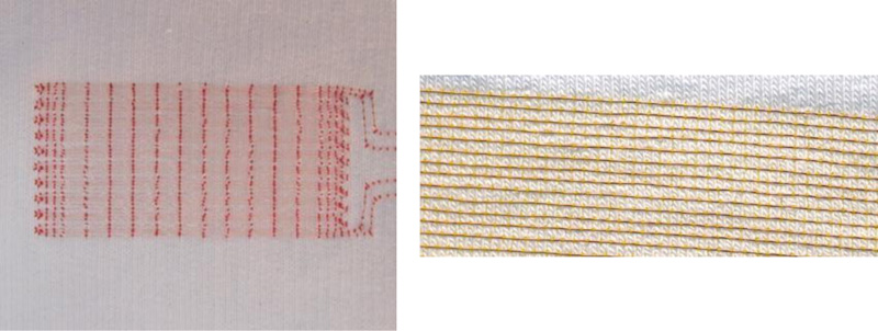
Left: Photograph of a textile with sensor array and clearly visible red embroidery upper thread. The sensor array consists of two insulated, very thin copper wires largely running in parallel to each other as double meanders, stitched onto the textile using asymmetric double lockstitch. The double meanders run here in ten loops towards the longer side, i.e., the length (L) of the sensor array. This array can be well stretched perpendicular to it (towards its width (B)).
Right: Photograph of an area of textile embroidered with an insulated copper wire using asymmetric double lockstitch.
Adequate monitoring of the healing of surgical wounds with functionalized textile dressings requires at least the peri-vulneral detection of any:
(1) Increase in temperature – as an indicator of inflammation;
(2) Sudden increase in moisture/wetness – as an indicator of bleeding or seroma discharge from the wound; and possibly
(3) Elongation – as an indicator of an increase in volume caused by internal haemorrhage or seroma formation.
These variables can all be measured with textile sensors [8, 9].
2.3.1. Temperature Measurement
In a current-carrying conductor, because the ohmic resistance R is essentially a function of temperature-dependent changes in electrical conductivity, it can be used as a measure of temperature. The correlation between resistance and temperature over a temperature range of a few degrees Celsius can be expressed in the following approximation involving the temperature coefficient α0 , a reference temperature T0 , and the reference resistance R0 at a temperature T0 [10]:
 |
The sensitivity (change in measurand) ΔR/ΔT (dR/dT) is:
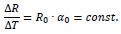 |
The change in ohmic resistance R due to temperature T is constant and rises with increasing reference resistance for a given material.
2.3.2. Moisture Determination
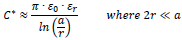
If two insulated, current-carrying conductors run parallel to each other (at least in part, e.g., as a meander or spiral) in a textile, in functional terms they form a planar (two-dimensional) capacitor with a capacitance C. The dielectric of this capacitor is predominantly formed by the textile, air and/or moisture between the conductors. In a dressing, an increase in particular in the amount of water due to the secretion of tissue fluid or blood leads to a significant change in the relative dielectric (εr,dry ≈ εr,textile ≈ εr,air ≈ 1, and εr,moisture = εr,water ≈ 80), altering the capacitance C.
Two wires with radius r running parallel to each other with spacing serve as a very simple model to estimate the determinant correlation which can be expected. At low frequencies, using the relative permittivity εr of the insulator as well as the electric field constant ε0 (= 8.85 . 10–12 As/Vm), the capacitance constant C* (capacitance per length of conductor) can be estimated as follows [10]:
 |
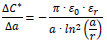
The sensitivity ΔC*/Δεr (dC*/dεr) is:
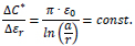 |
The change in capacitance C due to a change in relative permittivity εr in this model is constant; it is correlated to the ratio of a to r. The capacitance values rise with increasing permittivity.
The correlation with the spacing between the conductors ΔC*/Δa (dC*/da) can be estimated as follows:
 |
The change in capacitance C due to a change in geometry, for example, by increasing the spacing a, is not constant but negatively reciprocal (inverse) to a. The capacitance values decline as the distance increases compared to the change in capacitance C due to a change in permittivity.
2.3.3. Determination of Elongation
If, for example, only one meandering insulated electrical conductor in the textile is considered, in functional terms, it forms a planar (two-dimensional) coil with an inductance L. If the geometry is changed – if for instance the spacing increases due to the elongation or upwards bulge (third dimension) of the dressing – this inductance changes.
The very simple two-wire model introduced above can also be used to estimate the expected determinant correlation in connection with inductance. At low frequencies, given the relative permeability µr of the insulator (≈ 1) as well as the magnetic field constant µ0 (= 4π . 10–7 Vs/Am), the inductance constant L* (inductance per length of conductor) can be estimated as follows [10]:
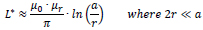 |
The correlation ΔL*/Δa (dL*/da) can be estimated as:
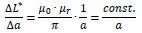 |
The change in inductance L due to elongation (change in geometry) is reciprocally proportional to the spacing a without a elongation.
Liquids (wound fluid or blood) do not affect the relative permeability µr and therefore have no influence on inductance either.
2.4. Positioning of Sensor Conductors in a Functionalized Dressing
(1) To determine the temperature using a textile sensor, the sensor conductors need to be as long as possible to maximize the changes to electrical resistance. The two conductors described below should preferably be connected in series. Although an insulating layer delays the change in temperature of the conductor and thus the measurement of temperature, the sensor conductors should still be electrically insulated to avoid short circuits caused by tissue fluid or blood.
(2) To determine moisture with a textile sensor, electrically separated and insulated sensor conductors arranged in parallel to each other are required. To achieve the highest possible measurable changes in capacitance, the sensor conductors should be arranged to include sections that are as long as possible and in parallel to each other – for example, by creating as many double meander loops as possible.
(3) To determine elongation, only one insulated conductor (of the above-mentioned two conductors running in parallel) is required. To achieve a large measurable change in inductance, this conductor should have as many (meander) loops as possible (which is also conducive to moisture determination).
Once functionalized in this way with sensor conductors consisting of insulated sensor yarn, the dressing represents a large, flat sensor, an example of which is shown in Fig. (2).
2.5. Assumptions and Estimating the Expected Changes in Measured Variables
(1) Temperature: All wound healing (including non-infected wounds) equates to a local inflammation and is accompanied by a temporary increase in temperature of the wounded skin [11-13]. Following the implantation of artificial hip or knee joints, Romano et al. [14] found the mean local temperature difference between the skin around the surgical wounds of 40 patients and skin on the non-operated opposite side to be up to about 4 °C in unimpeded healing. A reliably distinctive change in wound temperature should therefore be about 0.25 °C (an arbitrarily set figure), requiring a measurement repeatability of about ± 0.1 °C.
(2) Moisture: We found no information in the literature on the amount of fluid secreted by a wound not healing regularly. Because of the enormous measurement effects to be expected, it must be able to detect the moisture penetration of the carrier textile between the two sensor yarns over a section measuring 0.1% (again, an arbitrarily determined amount) of the length of the sensor wire in the area of the wound. This corresponds to a quantity of liquid of a few microlitres, which is presumably well below any clinical relevance.
(3) Elongation: There is no information in the literature either on the degree of elongation of post-operative wounds in the event of haemorrhage or seroma formation. Therefore, relative elongation of the carrier textile between the edges of the sensor of about 5% needs to be detectable in the wound area – an amount that results when the wound suture is raised by a few millimetres. This assumption is also purely arbitrary and may be below any clinical relevance.
3. MATERIALS AND METHODS
3.1. Textile Sensors
consisted of a textile backing (‘white/heavy/elastic cotton jersey, type SW 45542-5003’, 95% cotton, 5% elastane, with 30% reversible stretch) and ‘CU-ETP 99.95%’ electrical conductors made of insulated enamelled copper wire (Elektrisola Dr. Gerd Schildbach, Reichshof / D). The textile sensors were contract-manufactured by a university textile institute as double meanders by means of asymmetric double lockstitch (pick-up embroidery with a seam thread as the upper thread, electrical conductors as the lower thread) using a ‘JF 0111-500’ programmable embroidery machine (ZSK Stick-Maschinen, Krefeld / D).
The parameters of the sample dressings are (1) the diameter of the electrical conductors (d), (2) the distance between an electrical conductor and the next (parallel) conductor (a), (3) the spacing of the embroidery seams (upper thread loops) along a conductor (b), and (4) the length and width of the double meander sensor array (L, B).
The following were measured by way of example:
- Sample type for moisture measurement: d = 0.071 mm, a = 1 mm, b = 1 mm, L ∙ B = 80 mm ∙ 40 mm
- Sample type for elongation: d = 0.071 mm, a = 0.5 mm, b = 3 mm, L ∙ B = 40 mm ∙ 30 mm
3.2. Measuring Devices
A ‘Precision Impedance Analyzer WK 6500/5 B’ (Wayne Kerr Electronics, Chichester / UK) with gold-plated terminals in 4-wire technology was used to measure ohmic resistance R, electrical capacitance C, and electrical inductance L.
The temperature was measured using Pt100 sensors in 4-wire technology together with a Pt100 PC-based data logger measuring system ‘PT-104’ (Pico Technology, obtained from PSE Priggen Special Electronics, Steinfurt / D)
4. RESULTS
4.1. Technical Skin Models
To measure sensor dressings, suitable measuring stands are required that simulate the properties of the human skin to be measured by the wound dressing, i.e., technical skin models.
We did not find any commercially available technical models of the body surface with the main properties of the skin specific to the measured variables (above all, constant temperature in certain areas but varying locally as well as surface and material properties) for systematic investigations. Similarly, no descriptions of assemblies by other researchers for comparable purposes were found that could have served as a model.
4.1.1. Requirements for the Technical Skin Models
4.1.1.1. Temperature Measurement
The function of textile sensors, which are components of a wound dressing, is not to determine a homogeneous temperature beneath the sensor array, but to identify an increase in temperature beneath a localized area (an area of inflamed skin, around a suture, e.g., 34–35 °C) while the temperature of the remaining area under the skin (covered with clothing or a wound dressing) remains roughly constant e.g., about 32 °C) [13]. This must be simulated by the skin temperature model.
4.1.1.2. Moisture Detection
A (change in the) presence of (liquid) water in the dressings is to be detected with capacitive measurement. This requires a material environment corresponding – at least approximately – to the environment when the dressing is placed on a patient’s skin. This is because materials with different electrical permittivities may affect the measurements. Owing to the unknown effect, placing sample dressings for moisture measurement directly on a table or on a plastic panel or wooden board (or similar) is out of the question, even if clearly interfering structures (e.g., a metal table frame) are sufficiently far away.
4.1.1.3. Measuring Elongation
Inductively and capacitively determining the electrical properties of the inductance and capacitance of planar (or almost planar) arrays of electrically insulated conductors is practically independent of the temperature in the area to be examined. The presence of potentially interfering materials nearby should, if possible, be avoided when designing the measuring stand or ruled out by comparative measurements.
4.1.2. Description of the Technical Skin Models
4.1.2.1. Technical Skin Temperature Model
In Fig. (2), the liquid (water) of a circulating thermostat (‘F 32-HL’, Julabo, Seelbach / D) flows through a U-shaped channel (diameter: 10 mm) in an aluminium block (B ∙ L ∙ H = 100 mm ∙ 100 mm ∙ 50 mm; flow rate: about 700 mL/min). The aluminium block is surrounded on all sides and at the bottom by porous foam insulation about 18 mm thick.
After a while, an equilibrium is reached between the heat supplied from the circulating water and the heat emitted into the environment on all surfaces, including the upper one. On the top of the block is a replaceable plate (L ∙ W ∙ H = 100 mm . 100 mm . 10 mm) made of black POM (polyoxy methylene, polyacetal), a poor heat conductor that has good mechanical working properties (heat transfer coefficient: λ = 0.31 - 0.37 W/(K·m)), with or without a slot (opening, L ∙ W ∙ H = 50 mm ∙ 5 mm ∙ 10 mm), where a cuboid of aluminium (Al) of the same size, acting as an excellent heat conductor (λ = 236 W/(K·m)), promotes heat transfer from the central aluminium block to the surface, thus simulating a warmer (‘inflamed’) skin suture (here: 50 mm ∙ 5 mm). To maximize thermal conductivity, the gap between the aluminium block and the aluminium cuboid is filled with about 2 drops of fine machine oil.
The theoretically different temperatures on the surfaces of the materials mentioned also depend somewhat on their location (due to the slightly different distance from the flowing hot water).
As close as possible below the surface (central distance: about 2 mm) there are some boreholes (diameter: about 3.1 mm) parallel to the surface for Pt100 temperature probes (diameter: about 3.0 mm) to measure the surface temperature. Again, good thermal conductivity in these holes is ensured by fine machine oil (about 1 drop in each hole).
4.1.2.2. Technical Skin Moisture Model
Human tissue (especially subcutaneous tissue and muscles) comprises more than 60% water. To simulate this, the surface on which the sample dressings lie during measurement should also consist mainly of water. A piece of plastic film (fish pond film, thickness: 1 mm) made of EPDM or PVC was chosen (in the absence of practicable alternatives) as a boundary layer (quasi as a skin substitute) above the water and stretched over a small basin (internal dimensions: 170 mm . 90 mm . 50 mm). The temperature-controlled water of a circulation thermostat (circulation thermostat ‘F 32-HL’, Julabo, Seelbach / D) flowed through the basin (flow rate: about 700 mL/min).
A Pt100 temperature probe was inserted through a small hole in the basin wall with its tip directly beneath the centre (distance: max. 1 mm) of the sample dressings lying on the foil. Schematic representations and photographs of the model are contained in Fig. (3). Water was added manually (by pipetting) with a piston-operated pipette.
4.1.2.3. Technical Elongation Model
Determining the electrical inductance and capacitance of planar (or nearly planar) arrays of electrically insulated conductors is practically independent of temperature in the area to be investigated, and the presence of potentially disruptive materials e.g., magnetizable metals) nearby can be avoided when designing measuring stands. Given this, a simple but evidently sufficient way to measure elongation is to hang up a sample dressing from one end and stretch it by suspending weights from the other end.
To hold the sample dressings in place, clamps that were as small and light as possible made mainly from light POM (mass: about 18 g) were used; see Fig. (4), top left. The elongation model with a sample dressing held between two such clamps and suspended for measurement is shown in Fig. (4), right.
Sample wound dressings were suspended from a laboratory stand with clamps on both sides and connected to an LCR meter to measure electrical capacitance or inductance. The terminals of the LCR meter were attached to the samples at a suitable height to avoid unwanted tensile forces (Fig. 4, right).
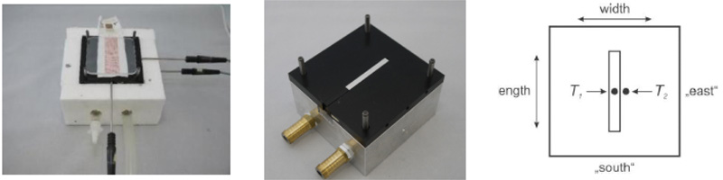
Left: The photograph shows the temperature model with foam insulation and a sample dressing (80 mm ∙ 25 mm) covered with two plexiglass plates on the measuring surface. On the right (‘east’) and in front (‘south’), the metal shafts of two Pt100 temperature measuring probes are visible. Their measuring tips are located in boreholes (‘south’) precisely below the centre of the measuring surface (measuring point T1) or (‘east’) about 5 mm to the right (measuring point T2).
Centre: The photograph shows the temperature model (without the foam insulation), the aluminium cuboid in the central slot of the POM plate, three boreholes on the right (‘east’) of the POM plate (the middle one leading to measuring point T2), and another borehole on the right (‘east’) in the aluminium block for temperature probes.
Right: Diagram of the surface of the temperature model (with slot filled with an aluminium cuboid) and projection of the locations of the reference or measurement temperatures T1 and T2 measured (centre of the temperature probes) about 2 mm below the surface.
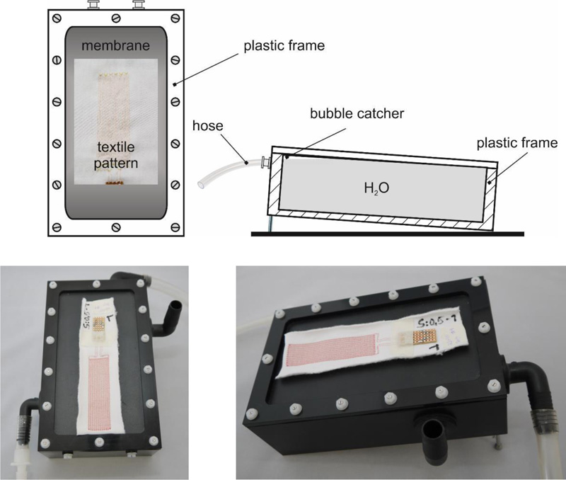
Top left: top view diagram. Top right: cross section diagram.
Bottom: Top view and right side view photographs. The inlet of the circulating water is at the bottom left (front), the outlet (overflow) is at the top right (rear). On the right of the model is an open pipe connection, which serves to continuously equalize the pressure of the gas space above the circulating water with the environment. On the surface of the plastic film is a sample dressing (ready for moistening with drops of water).
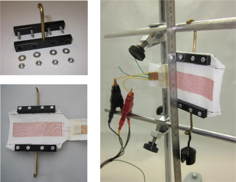
Top left: Individual clamp for sample dressings
Bottom left: Sample dressing with two clamps fitted.
Right: The elongation model with a suspended sample dressing stretched by a 100 g weight
A ruler was suspended centrally in the area of the sensor structures in front of the sample dressings in order to determine the elongation of the available section e (as well as the elongated section e + Δe stretched by a certain amount depending on the load) of the width, i.e., the distance (difference in value) between the clamps. To avoid parallax error, the distances on the ruler were always read from an exactly perpendicular angle. Electrical inductances and capacitances were each measured after a few seconds (to allow the entire array to mechanically “come to rest” after manipulation).
When a sample wound dressing is suspended “without” mass loading (m = 0), the distance e between the clamps (e(m) = e(m = 0) ≡ e0 ) is the portion of the width (B) of the sample that can be stretched laterally between the clamps when weights are applied, since it is not in the area of clamping between the jaws of the clamps. This distance e is:
 |
where
m Mass of the weights attached (weight force FG = m · 9.81 m/s2)
e0 Distance e without suspended mass (m = 0)
Δe Elongation, i.e., increase of the distance e by a suspended mass
The relative elongation is:
 |
The weights for elongation (50 or 100 g) had a measured relative deviation from the nominal mass of < 0.18%.
4.2. Important Properties
4.2.1. Temperature Model
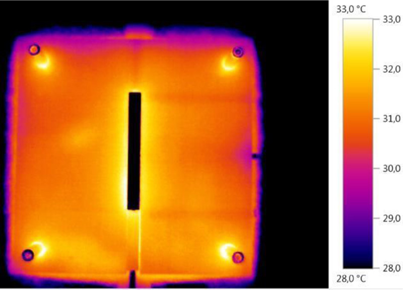
Fig. (5) shows a thermal photograph of the surface of the temperature model.
The surface temperatures of the POM plate are clearly inhomogeneous (patchy). For example, boreholes for Pt100 probes (especially those at lengths 25 mm and 75 mm) positioned just below the surface on the right are clearly visible.
Fig. (6) shows temperatures of the temperature model in the boreholes arranged perpendicular to the longitudinal direction (at half length) directly below the surface of the model, both up to the aluminium thermal bridge and on the corresponding points in the uninterrupted (and not bridged with an aluminium cuboid) POM plate.
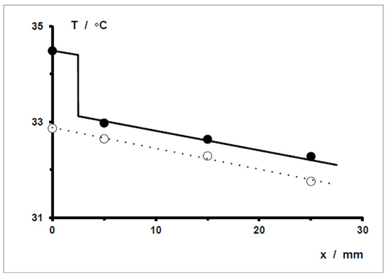
ΔT(x = 2.5 mm) ≈ 1.25 °C and ΔT = T1 (aluminium) – T2 (POM) ≈ 1.5 °C.
4.2.2. Moisture Model: Electrical Capacitance as a Function of Water Volume
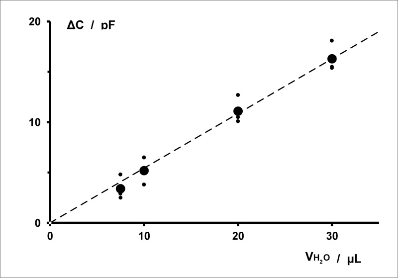
Fig. (7) shows the correlation between the change in the electrical capacitance of a sensor array and the volume of distilled water applied to and in a sample textile wound dressing. The correlation determined is strictly linear.
Smaller volumes were not used because 7.5 μL is the smallest volume of water that (subjectively) can be reliably pipetted with the pipette used.
4.2.3. Elongation Model: Correlation between Elongation and Elongation Force
As an example, the correlation between the elongation of a sample dressing type and the elongation force exerted by the attached weights (mass m) was investigated. Fig. (8) shows a graph of this correlation up to m = 100 g, with elongation of up to about 14%. The measurements (positive) of relative elongations plotted without elongation mass are recorded after the removal of the weights (after final stretching). They represent a certain deformation of the sample dressings (irreversible elongation) due to preceding stretching.
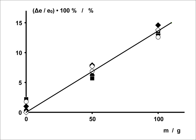
Diameter of the copper wires: d = 0.071 mm. Spacing between the copper wires: a = 0.5 mm. Embroidery spacing: b = 3 mm.
Length · width of the sensor array: L · B = 40 mm ∙ 30 mm.
5. DISCUSSION
The technical skin models have each been specifically designed to enable the measurement of one relevant parameter used to characterize the condition of surgical wounds when treated using textile dressings with purely textile sensors. In each case, these models have properties that are important for the type of measurement concerned (they simulate this skin property to the wound dressings) without (as far as we are aware) possessing any properties that could disrupt these measurements.
There is a significant difference between the models. The temperature correlation of electrical resistance is a property of the wire and – at a homogeneous temperature as well as with sufficient contact between the sensor wire and the heat-controlled surface of the skin model – is independent of its geometrical structure on a sample dressing (although on the other hand, the wire structure affects the total electrical resistance at different temperatures beneath the sensor array). The temperature model of the skin, therefore, clearly simulates by itself the essential property of locally varying temperature. The measuring results of sample dressings are not required for characterization.
The other two technical skin models necessarily require functional measurements of certain sample dressings by way of example for meaningful description. Characterization of the models by themselves is meaningless. The skin temperature model simulates a completely localized inflammation with a slight increase in skin temperature on a limited area of skin. The temperature difference simulated by the model corresponds to the order of magnitude for measurements on wound dressings. Whether it also corresponds to clinical conditions will be ascertained in future studies on patients.
The moisture model simulates a secretion of (minimal volumes of) blood or lymph from the wound suture into wound dressings, which are very sensitive to this variable.
The elongation model simulates the elongation of dressings whose lateral edges are fixed to the skin e.g., by taping) by an increase in volume (i.e., swelling) of the peri-vulneral tissue caused for example by haemorrhage or the formation of seroma. The elongation of the sample dressings measured of up to about 14% with an elongation force of 98 N (m = 100 g) depends of course on the carrier textile used and can be adapted as required by choosing a different textile.
CONCLUSION
The functional results of the moisture detection shown by way of example correspond to moisture measurement and also provide proof of concept of the sample dressings used with a sensor array in the form of a double meander. The results of elongation detection do not contain any electrical measurements. Instead they are only suitable for indicating their basic principle: linear elongation as a function of the elongating force. This was demonstrated here for the elongation of sample dressings with a sensor array in the form of a double meander.
LIST OF ABBREVIATIONS
| EPDM | = Ethylenpropylendien Synthesis Caoutchouc |
| POM | = Polyoxy Methylene |
| PVC | = Polyvinyl Chloride |
ETHICS APPROVAL AND CONSENT TO PARTICIPATE
Not applicable.
HUMAN AND ANIMAL RIGHTS
No animals/humans were used for studies that are the basis of this research.
CONSENT FOR PUBLICATION
Not applicable
AVAILABILITY OF DATA AND MATERIALS
The data that support the findings of this study are available within the article.
FUNDING
The project ‘Full-textile sensor wound dressings’ was kindly funded by the DFG German Research Foundation under project number ZI 1518/3-1. Publication fees were funded by PHWT - Private University for Economics and Engineering, Germany.
CONFLICT OF INTEREST
The authors declare no conflict of interest, financial or otherwise.
ACKNOWLEDGEMENTS
Declared none.