All published articles of this journal are available on ScienceDirect.

An Integrated Hardware and Software Application to Support Wound Measurement Using a 3D Scanner and Image Processing Techniques
Abstract
Aim:
To build wounds volume(3D) and area(2D) measuring system and device.
Background:
The measurement of the wound depth has been troublesome due to difficulty fo the procedures, physicians mostly avoid inspecting the wound depth as it could cause wound inflammation and infection.
Objective:
To build a contactless device for measuring wound volume and develop the system to support the wound treatment process which offers precise measurement and wound healing progression.
Methods:
Build a machine to control and stabilize 3D-scanner over the wound using a servo motor and apply the image processing technique to calculate the wound's area and volume. Comparing the machine accuracy by using Archimedes's principle testing with various wound model sizes, made from folding clay and pork rinds.
Results:
The device and system generate an error value of less than 15% which is within a satisfactory level.
Conclusion:
Knowing the wound depth is vital for the treatment, direct contact to the wound area can cause inflammation, infection, and increase time to heal. This device will help physicians to get more insight into the wound and improve the treatment plan for the patients.
There are certain limitations to be considered for future work. Firstly, different software components used in the image processing and estimation process could be integrated to enhance user experience. Secondly, it is possible to apply Machine Learning techniques to identify the wounded area on the wound image file.
1. INTRODUCTION
In order to determine the most appropriate treatment of a wound, the precise characteristics of the wound, including the size of the wounded area and its depth, and healing progress are the primary focuses of the physician [1, 2]. As the wound naturally recovers from its deepest part [3], the wound volume can, therefore, be used to indicate the wound recovery condition, as well as, how effective the treatment is. In Thailand, physicians mostly rely on manual approaches for measuring wound sizes, such as using rulers, transparent Visitrak films, and 2D camera [4]. Diagnosing the wound at its depth is generally avoided as direct contact between tools and the wound might cause inflammation. Unfortunately, there have been cases in which physicians decided to opt-out of the current treatment although it has been effective as the recovery was not visible on the surface.
Apart from not being able to diagnose the wound at depth, other challenges lie in the process of wound treatment. In terms of data management, data generated during the treatment processes are manually recorded on paper or separately saved as electronic files. Some operational parameters, such as the amount of lactated Ringer’s solution needed for the burns, are partly sight-estimated based on the wound surface area. Moreover, past treatment records are stored in various forms in different systems, thus making it difficult to compare past records to observe changes over time.
Our research and development attempts aim at inventing an integrated solution to facilitate the physician’s workflow of wound treatment. This covers the process of measuring wound volume, determining treatment, handling data electronically, and presenting associated data in proper forms. Our proposed solution integrates a newly invented machine that can accurately measure the wound size and volume, and a software that collects, analyses, and presents data essential in the treatment process. Specifically, the software also calculates certain operational parameters used in the treatment, instead of relying on sight estimation. The design of the wound measuring machine is presented in our previous work [5], while the software platform and user interface design can be found in a separate article [6].
This paper presents the manifestation of the proposed machine design, integrated successfully with the proposed software solution. To the best of our understanding, this is the first machine that allows contactless estimation of wound volume with satisfactory accuracy. The system was tested against simulated wounds of various shapes, both regular and irregular, in order to verify its measurement accuracy. The test showed that our system is approximately 90 percent accurate compared to Archimedes’ principle [7] for measuring object volume. The system was found to be useful for simplifying wound treatment workflow, especially in terms of contactless wound measurement, result accuracy, as well as data synthesis and visualization.
The paper is organized as follows. Section 2 outlines various traditional methods for wound measurement. Section 3 explains the digital image processing technique. Section 4 describes the design of our hardware. The next section discusses the software design and our approach to calculate the amount of lactated Ringer’s solution needed for the burn. Section 6 presents the workflow of “WoundCal” programs designed to estimate the area and volume of the wound followed by the experimental design to test the estimation accuracy and the results. The paper ends with conclusions and suggestions for future work.
2. MATERIALS AND METHODS
2.1. Traditional Wound Measurement
This section outlines the general methods used for measuring wound volume [4] and then rationalizes the choice of our hardware design solution.
2.1.1. Using a Ruler
A common way to measure its width and depth is using a ruler and a cotton-tip applicator to calculate wound volume. The volume is then estimated by multiplying the widest width of the wound with the longest length and the deepest depth.
2.1.2. Using a Visitrak Film
The error found in the first method can be reduced by using a Visitrak film, a tablet transparent film for measuring wound surface area [8, 9]. Then, the volume is calculated by multiplying the area with the wound depth.
2.1.3. Using a 2D Camera
The Visitrak film offers roughly 94% accuracy. A 2D camera is used to improve the accuracy of measuring the area of small wounds [10-13]. To use this method, pictures of the wound are taken with a reference object and then, by using an image processing application, such as ImitoMeasure [14] and ImageJ [15], the wound’s width and length are determined.
2.1.4. Using a 3D-Scanner
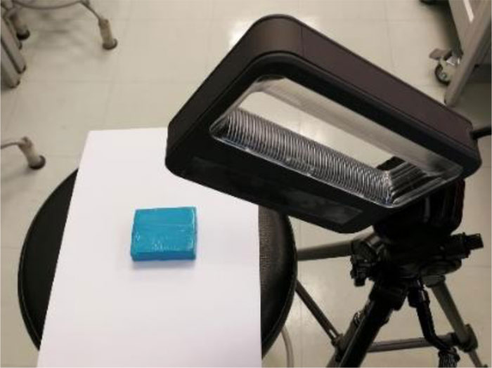
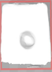
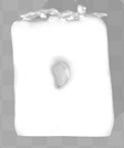
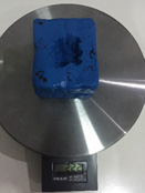
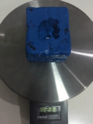
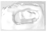
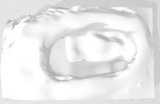
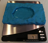
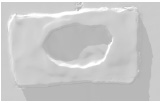
Compared with the tools, wounds can be more accurately measured using a 3D scanner [16]. With a 3D scanner, wound depth can now be captured entirely, and the volume can, therefore, be calculated by integrating small slides of the wound with the actual depth of each slide [17, 18]. Fig. (1) displays the use of a 3D scanner to scan the blue object. However, it is required to move the scanner around the object. The unsteady movement of the scanner may result in an incomplete 3D-image model, as illustrated in Fig. (2).
2.2. Digital Image Processing Technique
Digital image processing consists of many ways of processing, for example, using color pixels from different areas to process or combining many areas to process to observe the shape or image characteristics. This processing method has been applied to many sectors, such as medical, security, and object detection in the industrial sector.
There are many color systems used for image processing nowadays, depending on the objective of using it. However, they use the same standard concept which replaces pixels in a 3D plane point by using a reference axis for that color in the plane of each axis, with each axis independent of each other. In this research, the RGB color system is used which consists of red, green, and blue color.

RGB color system is an additive color system that combines red, green, and blue light to create the colors. If these three colors are not present, black color is observed. On the contrary, if all three colors are present, then white color is observed. This is different from the CMYK color system. CMYK is a subtractive color system in which the surfaces appear to be of certain colors because of the wavelengths of light they absorb and reflect.
Apart from the color system, to calculate pixel, we use file .bmp or Bitmaps to process the calculation. Thus, it is important to understand how Bitmaps work as explained in section 3.1.
2.2.1. Bitmaps File Format
Bitmaps are defined as a rectangular mesh of cells called pixels, with each pixel containing a color value. They are characterized by only two parameters, the number of pixels and the information content per pixel. There are other attributes that are applied to bitmaps, but they are the derivations of these two fundamental parameters.
Bitmaps are always orientated horizontally and vertically. Pixels should be considered square, although they may have other aspect ratios in practice in which the bitmap file structure. In the majority of situations, bitmaps are used to represent images on the computer.
One bit is the smallest possible information content that can be held for each pixel. The pixels with a 0 are referred to as black, while pixels with a 1 are referred to as white. Where 0 is mapped to one color, 1 is mapped to another color. 1 byte of storage results in 256 different shades. If these states are mapped onto a ramp of greys from black to white, the bitmap is referred to as a greyscale image. 0 is normally black and 255 is white. The grey levels are the numbers in between, for example, in a linear scale, 127 would be a 50% grey level
In 24-bit RGB format, there are 8 bits allocated to each red, green, and blue component. In each component, the value of 0 refers to no contribution of that color, while 25516 refers to a fully saturated contribution of that color. Since each component has 256 different states, there are a total of 16777216 possible colors.
2.2.2. Resolution
Resolution is an attribute of a bitmap that is necessary when visually viewing or printing bitmaps because pixels by themselves have no explicit dimensions. Resolution is normally specified in pixels per inch but can be in terms of any other unit of measure. Most printing processes retain the pixels per inch (DPI) units for historical reasons. The resolution may be specified on devices with N x N rectangular pixels as two numbers, the horizontal and vertical resolution. The concept of resolution being independent of the information content of a bitmap is very important. Given a constant color depth, the information content between different bitmaps is only related to the number of pixels vertically and horizontally. The quality, however, when the bitmap is displayed or printed depends on the resolution. Since the resolution determines the size of a pixel, it can also be used to modify the size of the overall image. As an example, consider one bitmap which is 200 pixels horizontally and 100 pixels vertically. If this bitmap is printed at 100DPI, then it would measure 2 inches by 1 inch. However, if the same bitmap is printed at 200 DPI, then it would only measure 1 inch by half an inch.
2.2.3. The Pixel Reading Technique
The image resolution affects the number of pixels related to the area. Therefore, the pixel reading technique is used to find the image area. If the resolution is equal to 1 PPI (Pixels per inch) it means the size of 1 pixel is equal to 1 square inch but if the resolution is equal to 8 PPI, then 1 inch will contain 64 pixels.
If we know the image resolution, then we can get the area by using pixel reading. Therefore, if we want to find the image volume, we can use Equation 1.
 |
(1) |
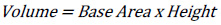
There will be no complication in finding the area and volume if the images are in geometrical shape. The standard area equation (Equation 1) can be used to get the base area and the volume can be found by multiplying it by the height.
The resolution of 8 PPI is equal to 8 x 8 x 8 pixels or 1 inch3 or 15.625 cm3. As shown in Fig. (3a), the volume will be equal to 2 x 2 x 2 pixels 0.015625 inch3 or at least 0.244140 cm3 compared to the resolution of 8 PPI. While in Fig. (3b), the same result is observed even though the shape is different. By comparing the volume of Fig. (3b) (1 x 2 x 4 pixels) to the resolution of 8 PPI, the volume is found to be 0.015625 inch3 or 0.244140 cm3
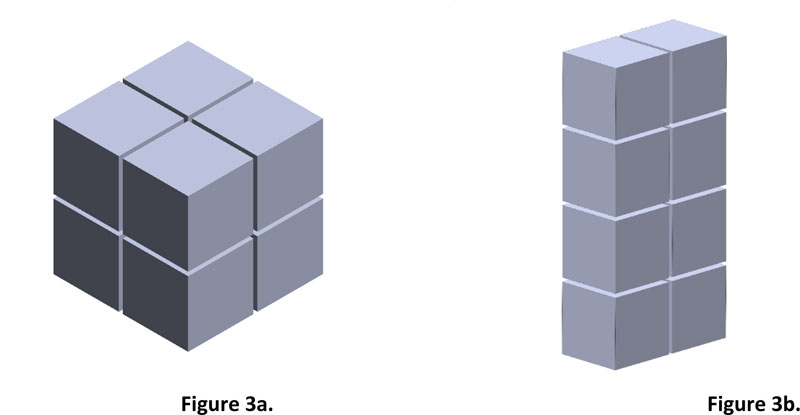
The method of finding the area and volume of geometrical shapes can be applied to irregular shapes, but high image resolution must be used to get accuracy.
If the image has a resolution of 8 PPI which is equal to 64 pixels or inch2, then from Fig. (4), 275 pixels will be equal to an area of 4.297 inch2 or 26.856 cm2. However, finding the volume of an irregular shape is different from a geometrical shape because of its concave curve and height. Therefore, to get the volume accuracy of irregular shape, the image must be divided into layers. The smaller the height range, the more accurate the result. Fig. (5) shows compare the simulated irregular shape between divided into 2 layers divided into 6 layers.
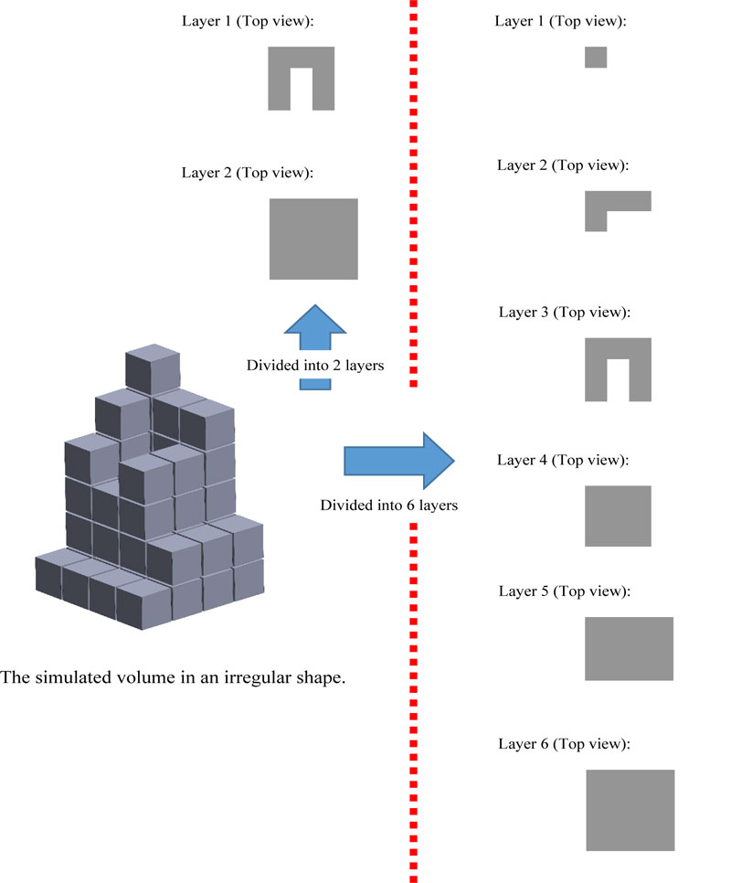

Hence, if the image has a resolution of 8 PPI, then according to 2 layers, it will have a total of 69 pixels, which is equal to 1.078 inch3 of volume, while according to 6 layers, it will have a total of 49 pixels which is equal to 0.766 inch3 of volume. The error percentage in 2 layers is equal to 40.73% compared to the error percentage in 6 layers which is equal to 0%. However, the number of divided layers affects the processing speed of the device.
3. THE MACHINE PROTOTYPE DESIGN
To facilitate the effective application of the 3D scanner for estimating wound volume, a prototype machine was designed and improved, as described in this section.
3.1. The Initial Design
The initial design was done based on Computer-Aided Design and Manufacturing using SOLIDWORKS software. In this version, a scanner would be mounted into a hardware platform in a box-like shape of 60*60*60 cm3 (Fig. 6). The scanner could move around the wound on x, y, and z-axis independently and steadily to generate 3D-model images. The machine uses stepper motors to control its movement. The design works for the wound located in certain areas, such as legs or arms. However, when that body part, such as a patient’s back and stomach, could not be placed inside the machine, the scanned could be performed put
3.2. The Improved Prototype
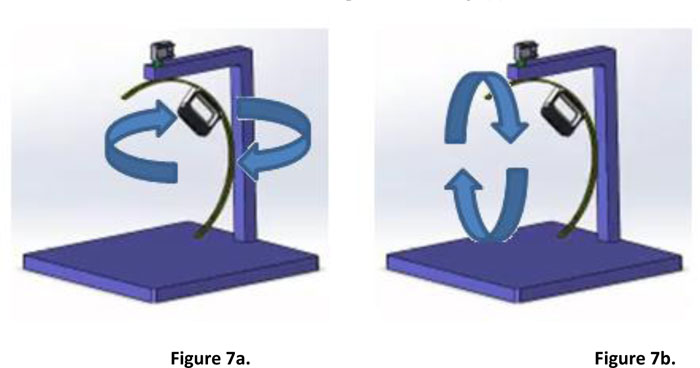
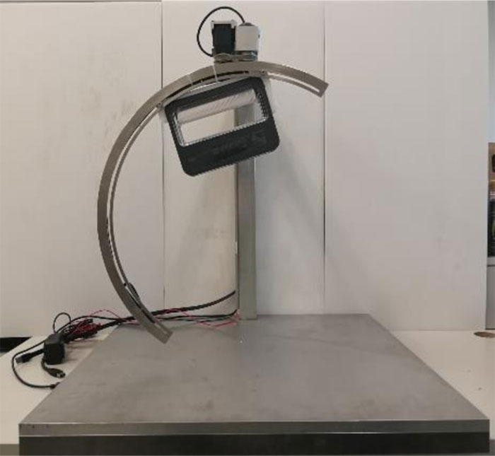
The second design removes the aforementioned constraint of the initial prototype. The scanner is attached to a half-circular rail, while the rail itself is attached to a servo motor [19] which allows it to move 360-degrees around the scanned object. Fig. (7) illustrates the hardware platform and the possible movement of the scanner. It is also possible to manually move the scanner through the rail to the desired position. The design has been built into a working prototype, as presented in Fig. (8).
4. A WOUND TREATMENT SOFTWARE
4.1. A System Workflow
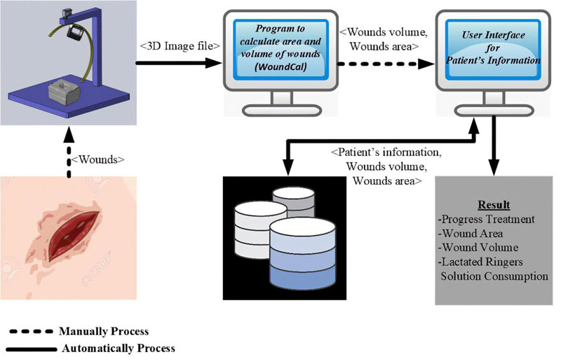
Our wound treatment system is composed of a hardware platform to perform wound measurement and a software application that handles corresponding wound treatment data. The software process is presented in Fig. (9). To use the system, the patient is asked to place the injured part of his/her body on the machine. The scanner is then moved around the wounded area to generate a 3D-image model. The image is sent to a standalone program to quantify the wounded area and its volume. Patient’s information, wound characteristics and relevant treatment records are then entered into the software application. The software supports data collection, primary data analysis, and data representation.
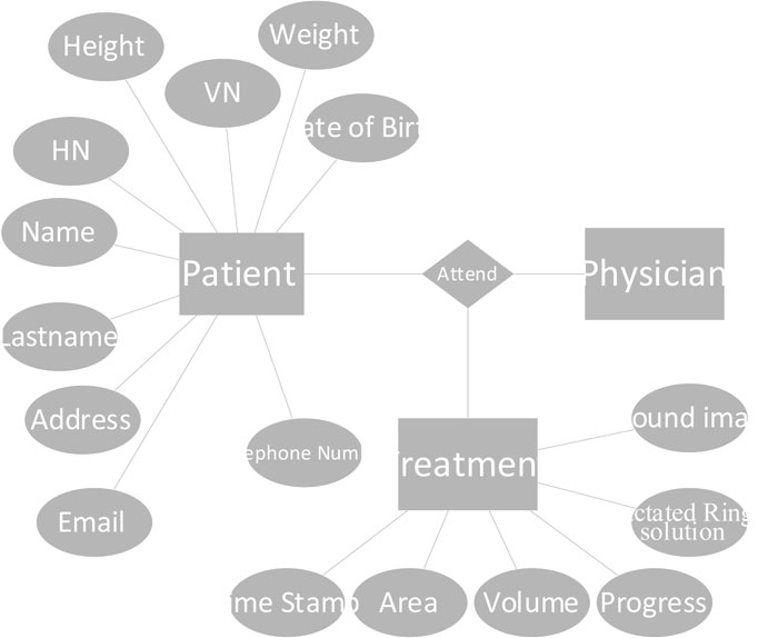
4.2. Database Design
The software based on an entity-relational (ER) model is presented in Fig. (10). In the current version, data collection is limited to the patient, biography, and wound treatment progression. The patient’s biography consists of basic information and personal contacts. The treatment table collects information about the size and volume of the wounded area and healing progression. Lactated Ringer’s solution is used during the treatment process to provide sodium, potassium, and calcium chloride to the wound. The consumption level of the solution is calculated partly from the size of the body. This value is given in the software. The database is implemented using Microsoft SQL Server 2014 [20]. The application is window-based, written in C# language.
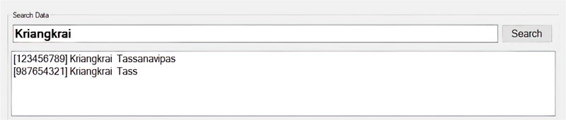
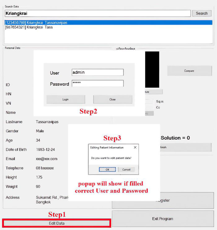
4.3. Functionalities and User Interface Design
The software is composed of patient management and wound treatment modules. The patient module provides create, read, update and delete operations. Patient search function considers the patient name, surname, citizen number, and hospital number (HN). As shown in Fig. (11), all the records match the search string which would appear in an output window so that the users can easily choose to see details of a specific patient. Fig. (12) displays the patient information input screen. The update operation requires special authorization, as illustrated in Fig. (13), where the user is asked to fill in his/her credentials.

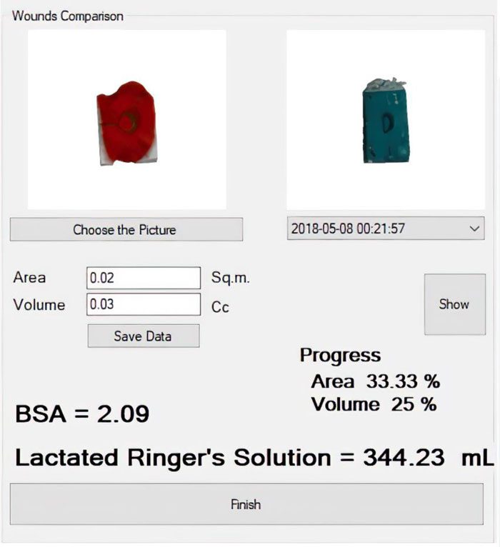
The second module handles treatment data and healing progression records. The wound image obtained from the 3D wound scanning machine is uploaded to this module to calculate the size, volume, and amount of lactated Ringer’s solution needed for the patient. It is possible to compare wound conditions in a discrete timeline, as shown in Fig. (14).
4.4. Lactated Ringer’s Solution Consumption
The required amount of lactated Ringer’s solution is generally calculated based on the percentage of the patient’s body surface area (%BSA) affected by the wound and the patient’s weight. The value is then computed by:
 |
(2) |
The process of %BSA estimation is summarized in Fig. (15). Traditionally, it is based on the rule of nines [21]. The body surface area belongs to each part of the human body. If, for instance, the arm gets injured, a physician would roughly estimate the %BSA of the injured area as the sum of nine. However, if the wound is located on the right leg, it would be estimated as the sum of 18. Certainly, different physicians may take a slightly different value of it.
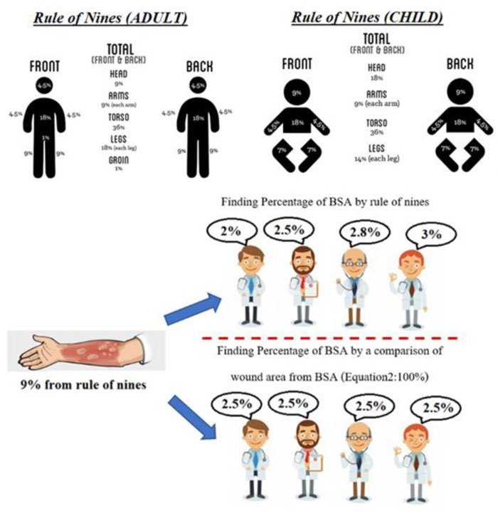
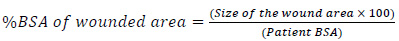
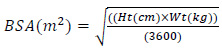
A more accurate calculation of the %BSA of the wounded area is proposed as:
 |
(3) |
The size of the wounded area is calculated from our software, while the patient BSA is calculated by:
 |
(4) |
where Ht and Wt refer to the patient’s height and weight in centimeter and kilogram, respectively.
5. WOUND VOLUME CALCULATION
The developed prototype is explained in the previous section. This section describes in detail the approach used to calculate the volume of the wound and how the test of accuracy was carried out. The 3-step procedure was as follows:
•Step 1: Developing wound models and creating their 3D-model
•Step 2: Creating very thin slices of the entire wound model
•Step 3: Wound size and volume estimation using a pixel reading method [22]
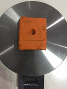
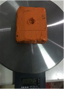
Step 1: Developing wound models and creating their 3D-model. Models of the wounds were developed to test the application of the prototype and its accuracy in measuring wound volume. Archimedes’ principle of liquid displacement was applied to calculate the base value of wound volume for comparison. An error rate of the machine-estimated values against the base values was identified.
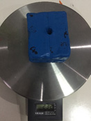
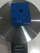
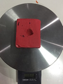
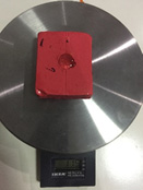
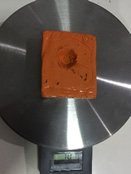
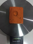
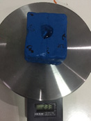
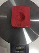
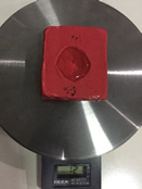
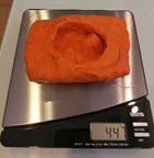
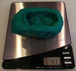
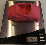
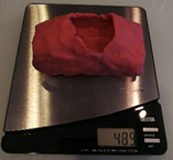
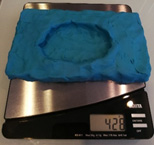
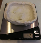
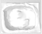
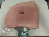
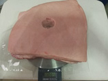
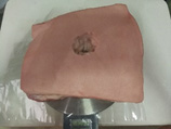
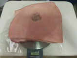
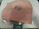
Two types of wound models were developed. The first kind was made from molding clay, while the other was made from pork rind. To create a wound on the surface of pork rind, a small part of the flesh was simply removed from the unit of pork rind. Examples of wound models are displayed in Table 1, along with their 3D models acquired from the 3D scanner attached to the rail.
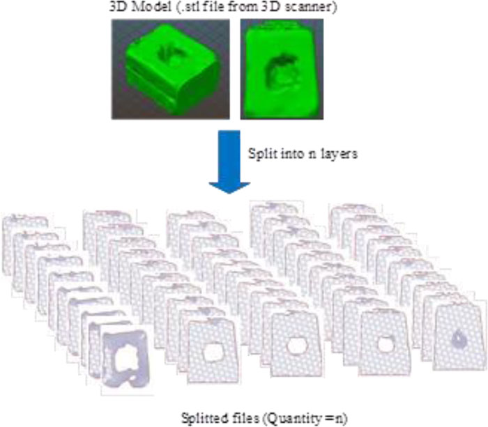
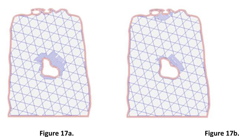
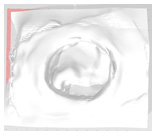
Step 2: Creating very thin slices of the entire wound model. The second step's input was the 3D model of the wound obtained from the small software module integrated with the prototype machine. The slicing technique was applied to prepare input for wound size volume estimation. Fig. (16) illustrates the collection of wound slices generated from the 3D models. The opensource program called Slic3r PE [23] was used to simulate the slicing model, which gave an image file for each wound slice. The slice thickness was set to 0.3 millimeters, which is the minimum value of thickness provided in Slic3r PE configuration. It is a fact that the flatter the slice, the more accurate the volume estimation. However, the thickness of 0.3 is considered sufficient, given the time required for the calculation and the level of accuracy acquired compared with the base practice. Nevertheless, the example of two consecutive wound slices is provided in Fig. (17) to illustrate the differences between the wounded areas.
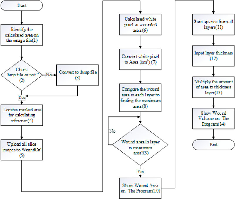
Step 3: Wound size and volume estimation using a pixel reading method. The estimation was done using a program “WoundCal” which was specifically developed for this purpose. The program flowchart exhibiting 14 activities involved in this step is summarized in Fig. (19). The input of this step was the images of each sliced layer of the wound obtained from the previous step. The process is as follows:
(1) a user identifies the slice with the largest wound size and then roughly indicates the wounded area on the image file by replacing that area with a black pixel. This can be done by using any image editor software. Fig. (18) illustrates an example of a wound slice image marked with a black pixel that covers the wounded area.
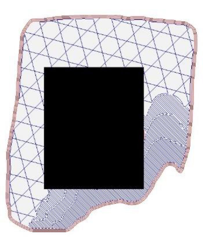
A critical analysis, interpretation, and evaluation of the obtained results are presented.
(2-3) upload the file from step (1) on WoundCal. The program transforms the image file to .bmp if it is not so.
(4) the program locates the area on the image that is marked with the black pixel from step (1). A two-dimensional (x, y) matrix is used to indicate the area. That is:
for every point of y,
identify the starting point and the ending point of x marked with the black pixel.
This marked area matrix is used as a reference as the program identifies the wounded area on each slice image of the wound.
(5) upload all the slice images of the wound on WoundCal
(6-7) the program calculates the size of the wounded area for each wound slice image. The wounded area can be identified by a white pixel as the result of the 3D scanner. The identified area is converted from pixels to centimeters (38 x 38 pixel is equal to 1 cm2)
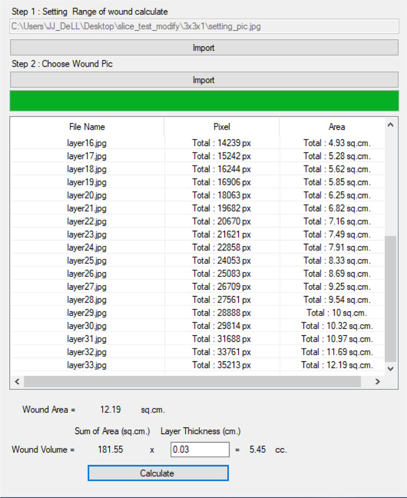
(8-10) the program identifies the wound slice with the largest size of the wound and uses that value to represent the size of the wound. This value is entered manually into the wound treatment application, as presented in Fig. (20).
(11-14) The program calculates the wound volume as follows:
 |
(5) |
with i refers to the wound slice. Thickness is set to 0.3 as mentioned previously. The wound volume is also entered into the wound treatment application.
6. THE EXPERIMENT SETUP
In the previous subsection, our approach to estimating the wound’s size and volume is explained in detail. The program “WoundCal” was developed to realize this approach. An experiment was then carried out for two primary objectives, firstly to measure how accurate the proposed method is compared to the estimation of wound volume based on the Archimedes’ principle of water displacement, and secondly, to assess usage limitation with respect to wound size.
6.1. The Wound Model
Seventeen wound models were developed for testing measurement accuracy and possible limitations. The first type of wounds was made from molding clay, while the second kind was made from pork rind. Pork rind was decided to be used considering that its skin represents, to some extent, the nature of human skin.
To ensure a variation of wounds, developed models have different sizes and irregular shapes. Out of 17 models, seven different address sizes of the wounded area, ranging from 1x1 cm2 to 3x3 cm2. The other seven models simulate different wound curves and uneven depth. The rest of the three model addressed bigger wounds and were made from pork rind, with the wounded surface area of 3x3 cm2 to 5x5 cm2. The deepest depth of the wound ranged from 1 cm to 3 cm.
6.2. Estimating Wound Size and Volume
Two methods were compared for estimating the size and volume of the wounds. The first one was our proposed method using the WoundCal program, while the other one was the base method using Archimedes’ principle of water displacement.
- Using our proposed WoundCal program. the process was as follows:
(1) Place the wound model inside the prototype machine for wound measurement, as shown in Fig. (16). The machine is connected to the computer where the 3D model and filename.stl can be saved as the input for the next step.
(2) Create slices of the wound 3D model using the Scli3e PE program. N image files of wound slices are generated.
(3) Identify the slice with the largest wounded area and roughly mark that area with a black pixel using any image editor program.
(4) Upload the marked image file to WoundCal.
(5) Upload the N image files of wound slices to WoundCal. This program calculates the volume of the wound.
•Using Archimedes’ principle. To estimate the wound volume based on Archimedes’ principle, the following steps were performed:
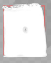
(1) weigh the wound model.
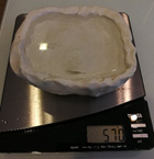
(2) fill water inside the wound.
(3) weigh the wound model again and then calculate the weight of filled water by water-filled model’s weight – initial weight. The weight of the water is equal to its volume since:
 |
(6) |
given that the density of the water is one. Therefore, the volume is the estimated wound’s volume.
7. RESULTS AND DISCUSSION
The estimation of wound volume was carried out based on the two methods mentioned previously. The Archimedes’ principle was used as the base values for comparison. Fourteen models of wounds were made from molding clay and the three models made from pork rind were experimental subjects. Table 2 presents the results of wound volume estimation.
The results show that the volume estimation for small surfaced wounds, such as 1 x 1 cm2, is more than 80% inaccurate. However, the WoundCal method provides acceptable volume estimation for bigger wounds. Wounds larger than a surface area of 1.5 x 1.5 cm2 are estimated to have less than 15 percent error. It can also be noticed that the bigger the wound, the more accurate the estimation.
Our proposed system is one of the first that tried to estimate wound volume using a contactless method. This approach is applicable to the pork rinds model which, to a certain extent, simulates the nature of human skin. The error found in the estimation can be associated with two primary causes. The first one is related to the weigh scale used in the Archimedes’ principle that allows for a minimum scale of one gram. The second cause might be the precision of the 3D scanners in capturing wound details.
| Wound Mockup before Water Replacement | Wound Mockup after Water Replacement | 3D Model(.stl) |
|---|---|---|
 Example1 Example11cm x 1cm x 1cm Weight 119 g |
 Example1 Example11cm x 1cm x 1cm Weight 120 g |
 |
 Example2 Example21cm x 1cm x 2cm Weight 232 g |
 Example2 Example21cm x 1cm x 2cm Weight 233 g |
 |
 Example3 Example31.5cm x 1.5cm x 1cm Weight 113 g |
 Example3 Example31.5cm x 1.5cm x 1cm Weight 115 g |
 |
| Wound mockup before water replacement | Wound mockup after water replacement | 3D Model(.stl) |
 Example4 Example42cm x 2cm x 1cm Weight 101 g |
 Example4 Example42cm x 2cm x 1cm Weight 103 g |
 |
|
Example5 2cm x 2cm x 2cm Weight 230 g |
 Example5 Example52cm x 2cm x 2cm Weight 233 g |
 |
 Example6 Example63cm x 3cm x 1cm Weight 116 cm3 |
 Example6 Example63cm x 3cm x 1cm Weight 121 cm3 |
 |
| Wound mockup before water replacement | Wound mockup after water replacement | 3D Model(.stl) |
 Example7 Example73cm x 3cm x 2cm Weight 222 g |
 Example7 Example73cm x 3cm x 2cm Weight 231 g |
 |
 Example 8 Example 8similar real wounds Weight 447 g |
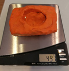 Example 8 Example 8similar real wounds Weight 497 g |
 |
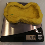
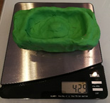 Example 9 Example 9similar real wounds Weight 429 g |
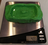 Example 9 Example 9similar real wounds Weight 486 g |
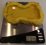
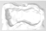
 |
 Example 10 Example 10similar real wounds Weight 433 g |
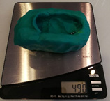 Example 10 Example 10similar real wounds Weight 490 g |
 |
| Wound mockup before water replacement | Wound mockup after water replacement | 3D Model(.stl) |
 Example 11 Example 11similar real wounds Weight 425 g |
 Example 11 Example 11similar real wounds Weight 489 g |
 |
 Example 12 Example 12similar real wounds Weight 428 g |
 Example 12 Example 12similar real wounds Weight 478 g |
 |
 Example 13 Example 13similar real wounds Weight 421 g |
 Example 13 Example 13similar real wounds Weight 570 g |
 |
 Example 14 Example 14similar real wounds Weight 434 g |
 Example 14 Example 14similar real wounds Weight 546 g |
 |
| Wound mockup before water replacement | Wound mockup after water replacement | 3D Model(.stl) |
 Example 15 Example 15Pork rinds model 3cm x 3cm x 3 cm Weight 1085g |
 Example 15 Example 15Pork rinds model 3cm x 3cm x 3 cm Weight 1089g |
 |
 Example 16 Example 16Pork rinds model 4cm x 4cm x 2cm Weight 1082 g |
 Example 16 Example 16Pork rinds model 4cm x 4cm x 2cm Weight 1088 g |
 |
 Example 17 Example 17Pork rinds model 5cm x 5cm x 2cm Weight 1072 g |
 Example 17 Example 17Pork rinds model 5cm x 5cm x 2cm Weight 1082 g |
 |
| Simulated wound | Estimated Wound Volume | % Error |
||
|---|---|---|---|---|
| Archimedes (cm3) |
WoundCal (cm3) |
|||
| Molding Clay Model | ||||
| Example1 1 x 1 x 1 |
1 | 0.2 | 80* | |
| Example2 1 x 1 x 2 |
1 | 0.12 | 98* | |
| Example3 1.5 x 1.5 x 1 |
2 | 1.73 | 13.5 | |
| Example4 2 x 2 x 1 |
2 | 1.76 | 12 | |
| Example5 2 x 2 x 2 |
3 | 2.58 | 14 | |
| Example6 3 x 3 x 1 |
5 | 5.45 | 9 | |
| Example7 3 x 3 x 2 |
9 | 10 | 11.11 | |
| Example8 similar real wounds |
50 | 55.21 | 10.42 | |
| Example9 similar real wounds |
57 | 62.38 | 9.43 | |
| Example10 similar real wounds |
57 | 62.69 | 9.98 | |
| Example11 similar real wounds |
64 | 71.74 | 12.09 | |
| Example12 similar real wounds |
50 | 46.33 | 7.34 | |
| Example13 similar real wounds |
149 | 158.16 | 6.15 | |
| Example14 similar real wounds |
112 | 119.08 | 6.32 | |
| Pork rinds model | ||||
| Example15 3 x 3 x 3 |
4 | 3.57 | 10.75 | |
| Example16 4 x 4 x 2 |
6 | 5.73 | 4.5 | |
| Example17 5 x 5 x 2 |
10 | 10.32 | 3.2 | |
CONCLUSION
With our goal to build a contactless system to support the wound treatment process, a prototype, integrating a machine and a software application that offers precise measurement of wound characteristics and handles wound healing progression, was created. Generally, a wound starts to heal from its bottom part, thus knowing the wound depth is vital for the treatment. Physicians typically insert a cotton-tip inside the wound to measure its depth. This may cause inflammation and increase the time to heal. A novel approach was proposed to estimate wound depth using a 3D model. A machine was built to control the stable movement of the 3D scanner over the wound using a servo motor. Then, the image processing technique was applied to calculate the wound’s area and volume. The method was tested with wound models of various sizes, made from molding clay and pork rinds. The accuracy of our approach was compared to the Archimedes’ principle of water displacement. The two methods were found to have less than 15 percent discrepancy. This level of accuracy is considered satisfactory, given that our work is among one of the first attempts to close this research gap.
There are certain limitations to be considered for future work. Firstly, different software components used in the image processing and estimation process can be integrated to enhance user experience. Secondly, it is possible to apply machine learning techniques to identify the wounded area on the wound image file. Lastly, it is suggested to create a cloud-based version of the software to allow easy access to the data and the application.
ETHICS APPROVAL AND CONSENT TO PARTICIPATE
Not applicable.
HUMAN AND ANIMAL RIGHTS
Not applicable.
CONSENT FOR PUBLICATION
Not applicable.
AVAILABILITY OF DATA AND MATERIAL
The parameters and test data regarding this research are available at https://bit.ly/2PA2PXZ
FUNDING
The authors would like to thank the Institute of Field Robotics, King Mongkut’s University of Technology Thonburi, Thailand for their great assistance provided during the research period.
CONFLICTS OF INTEREST
The authors declare no conflict of interest, financial or otherwise.
ACKNOWLEDGEMENTS
None.