All published articles of this journal are available on ScienceDirect.

MU-LapaRobot: A Corporative Surgical Robot for Laparoscopic Surgery
Abstract
Objective:
Development of surgical instrument robot (MU-LapaRobot) for assisting in conventional laparoscopic surgery.
Methods:
A robot was designed based on instrument movement for a conventional procedure. The mechanism mimics and constrains manipulation movement through the wire-driven transmission. It is flexible for robot end-effector, which has a lightweight and small size. The usability of the robot is passive and active robot tasks with an interconnected driving system. Three main parts of the robot are robot end-effector, transmission, and a driving system.
Results:
On a robot platform, a parameter for setup is robot posture. The adjustment of robot position and projection of manipulation area is influenced by the accuracy of movement. To verify movement, command and exact movements are measured. Compensation with the control system is improved in order to improve the accuracy of the system.
Conclusion:
MU-LapaRobot provides surgical instrument manipulation by using wire-driven transmission with an effective system and requires less interference in the conventional operation.
1. INTRODUCTION
In the past decade, Minimally Invasive Surgery (MIS) has been a popular surgical technique for operating in the abdominal cavity through small incisions. Nowadays, MIS has become a standard procedure in laparoscopic surgery, thoracic surgery, and stereotactic surgery. Most of the cases in laparoscopic surgery are cholecystectomy surgery. This procedure utilizes several small and long stick instruments and a laparoscope with light insert through a port on the patient's abdominal wall that is different from the conventional surgical procedures. CO2 gas is filled in the abdominal cavity to create more working areas for the manipulation of surgical instruments [1, 2]. The surgeon can view the abdominal cavity by a monitor beside the surgical table, which displays real-time images from a CCD camera system attached at the tip of the laparoscope. There are many benefits of MIS, such as small wounds on the abdominal wall, less blood loss, short-stay hospitals, and fast recovery. In several cases, laparoscopic surgery takes a longer period (two or more hours) that causes fatigue to the surgeon [3-5]. Although there are many benefits for the patients, it also has some limitations for surgeon, such as lack of direct palpation and visibility on organs, loss of tactile feedback from long stick instruments, motion constraint through a small incision, and lack of eye-hand coordination [6]. In general, the camera operator (first assistant) provides the right field of view based on the command from the primary surgeon. Table 1 shows the advantages of a surgical robot over human surgeon.
In the 1990s, ZEUS, the first robotic surgical system with high performance, had been available in the market with three serial-chain manipulators in planar robot arm configuration. Robot arms with surgical console performed successfully in fallopian tubes operation. An endoscopic camera is commanded by AESOP™ voice-controlled [7].
Nowadays, da Vinci, which has a surgical tool and combination system with high definition imaging and ergonomic design, is widely used in many countries [8, 9]. High performance of dexterous instruments provides a broad coverage of the surgical areas, including 3D vision system. In addition, a bulky system and cost are considered in practical use. The development of the compact size of the robot assistant was introduced, such as LER robot [10]. It was developed for holding an endoscope as a human assistant in minimally invasive surgery. It has a full motion range of 360 degrees with a small footprint in rotation with back-drivable motors.
However, a high performance active surgical robot that can perform quite similar to da Vinci is the REVEN robot [ 11 ]. The same principle is a remote operation, but the structure is small and stiff. Moreover, a MC 2 E, which is attached with a force sensor, provides force feedback to a user while controlling the robot [ 12 ]. A joint actuator provides a spherical workspace through a fixed fulcrum point on structure with difficulty to setup. According to remote transmission, a miniature component is selected, such as a small wire for transmission. A CURES robot is a two wire-driven joint transmission with a grasping instrument with the actuator in moving parts [ 13 ]. Inertia of mass from the actuator, which has a high torque, causes a non-smooth movement in normal speed. However, a full teleoperation robotic system requires training with a new system. Moreover, a high torque of the actuator is difficult to reconfigure a robot posture to the desired position.
Furthermore, many Minimally Invasive Robotic Surgery (MIRS) procedures have been developed on research such as small size [14] robot, a surgical robot with force feedback [13], telesurgery system, and single-port surgical robot [15, 16].
Therefore, the corporative robot is proposed for a laparoscopic surgery that requires less interference and training. A robot end-end effector that is lightweight and small footprint occupies over the patient. This study focuses on the design and development of the new laparoscopic surgical robot, called “MU-LapaRobot,” aimed to use in teleoperation by a surgeon for existing surgical tools and procedures.
2. MATERIALS AND METHODS
The robot is designed for cooperating with a surgeon instead of a remote commander in MIS. In terms of design, it should be compact, lightweight, with ease of use, and short setup time. The main purpose of the robot is to perform as a surgical instrument holder in any position of constraint movement and teleoperation driven by actuators. The workspace requirement is the important point; hence port placement is properly angled to each other. This surgery uses many types of instruments such as a laparoscope, grasper, dissector, scissors, forceps, and else, which should be sterilized. There are four degrees of freedom in surgical manipulation [17].
The movements are 1 DOF for rotation, 2 DOF for translation of instrument, and 3 and 4 DOF are the combination of two axes that generate cone space. Ideally, the tip of the instrument should easily reach the working area (approximately 15 cm or a half of instrument length) sleeve of the trocar about 10 cm within the abdominal cavity. The two instruments should form a 60˚ (from top to bottom) to 90˚ (from left-to-right) angle from the tips of instruments for the ergonomic approach (Fig. 1). The instrument tips should be at a working distance of 80 mm to cover the working area. From the study [10, 11], the recommended conical range of motion is 60˚ angle in tool operations called dexterous workspace, DWS and a full range of tool motion called extended dexterous workspace (EDWS) needed to move 90˚ in left to the right direction and 60˚ in the foot to head direction. In laparoscopic surgery, a procedure starts from port placement on the abdominal wall through which any surgical instrument should reach the target. The manipulation angle of 60 degrees is recommended for efficiency and performance [18-20].
| Professionals | Surgeon | Robot |
|---|---|---|
| Pros |  Outstanding decision Exceptional hand- eye coordination Admirable skill Intelligent to assimilate and act on several sources Straightforwardly expert Outstanding decision Exceptional hand- eye coordination Admirable skill Intelligent to assimilate and act on several sources Straightforwardly expert |
Exceptional symmetrical correctness Resistant to ionizing radiation Steadiness without tremble Distantly controlled Unpretentious by radiation |
| Console | Surgeon | Robot |
| Cons | Disposed to to exhaustion and carelessness Hand tremble bounds fine motion Cannot see through tissue Imperfect symmetrical accuracy Pretentious by radiation, contagion |
Incomplete hand-eye organisation Deprived judgment Cannot act in different circumstances Necessity of maintenance Costly |
2.1. Conceptual Design
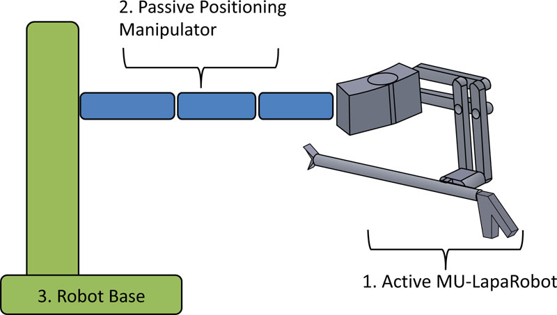
The kinematics of mechanism design constructs by joints that exhibit the DOF. Several mechanisms for the surgical robot are satisfied by pivot point constraints. Most robot manipulators have revolute joints or sliding joints [21, 22]. The conceptual design of a new instrument-holder assists in passive and active MISR. Surgeons can interact with the robot in passive mode and help to hold the instrument while operation with less interference dexterity of movement [17, 18]. A setup procedure starts from attaching the robot on the surgical bed. After positioning on the fulcrum point or incision point on the abdominal wall, the axis of the surgical instrument is passed through the fulcrum point in any direction of movement because a mechanical constraint fixes one point on the workspace. The robot arm section is used only in positioning an incision point. For this stage, robotic parts are designed and movement of a parallelogram and spherical mechanism is analyzed and used for mechanical constraint movement to create a virtual fulcrum point. These mechanisms are used to design the surgical robot to avoid collision around the incision. Next, the enhancement of MU-LapaRobot is applied to the driving system. The constraint movement of the surgical robot can be separated into three sections (Fig. 2), which are active MU-LapaRobot, Passive Positioning Manipulator, and Robot base.
2.2. Active MU-LapaRobot
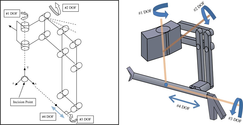
The end-effector of the robot arm is designed by using the mechanism, which provides the constraint movement (Fig. 3). The axis of movement is passed through the fulcrum point. The end-effector with 4 DOF is made lightweight by providing the wire-driven force transmission [17].
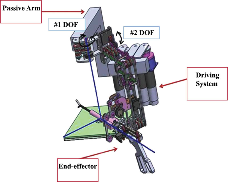
The constraint mechanism of the robot manipulator is safer compared to an open-chain robot manipulator. The parallelogram mechanism, which provides a virtual pivot point, is selected in robot structure. The conceptual design (Fig. 4) of a developed passive robot to an active robot has three main parts. Robot end-effector, passive arm, and driving system are the components of cooperative robot-assisted surgery.
2.3. Workspace Analysis
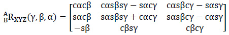
The workspace of the mechanism can be calculated by applying rotations to the mathematical equations, Rx(γ), then Ry(β), and then Rz(α), and the rotation matrices are shown in equation (1).
 |
(1) |
The coordinate frame or “frame”, denoted by {_} is the origin of that frame. The vector AP, targets coordinate with respect to frame A, BP, targets coordinate with respect to frame B and addition of vector in {A}, frame A, relative to {B}, APBorgin origin A, the origin of frame B is with respect to frame A. The addition of vector can be calculated by:
 |
(2) |
In order that the equation-(2) may write the mathematics given in the operator form by (1), and define a 4x4 matrix operator and use 4x1 position vector, so that (1) has a structure
 |
(3) |
 |
(4) |
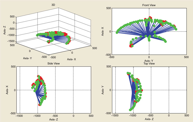
The 4x4 matrix in equation (3) is called a homogeneous transform. The construction uses to cast the rotation and translation of general transform into a single matrix form. These equations are used as a simulation of workspace to see the range of the robot end-effector. The cone shape is assumed as the working area in the abdomen. The red line represents the pathway of the surgical instrument in the range of the robot end-effector movement.
2.4. Tool Interchangeable
The end-effector of Active MU-LapaRobot has a system, which allows the surgeon to change the surgical instrument by themselves. There is a small structure, which is a socket for instrument installation. The additional parts are attached to a surgical instrument. There are three steps to change the instrument from the robot. First, a small lever locks the instrument at the translation joint. Second, the surgeon just presses a small lever to release the instrument. Finally, the instrument is pulled out of the socket and new instrument is changed in the socket step by step.
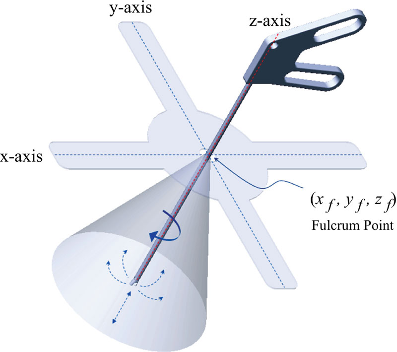
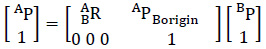
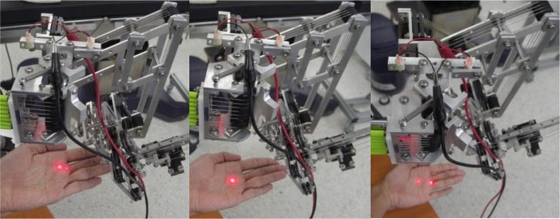
2.5. Laser Guidance of Positioning Port
In robot setup, a port placement can be identified by a laser pointer that provides a virtual fulcrum point on the surface (Fig. 5). Due to the virtual pivot point on the mechanism, it is not easy to check the fulcrum point. If two dots of laser pointer appear on the surface, it means that the robot is too close or too far from the abdominal wall. The transmission consists of a driving system that transmits a force by wire to robot end-effector. A Passive Positioning Manipulator works separately from Active MU-LapaRobot. Two wires connect from one end to another end for transmitting the rotation of joint movement in counterclockwise and clockwise. There are 3 rotations and 1 translation on end-effector.
2.6. Driving System
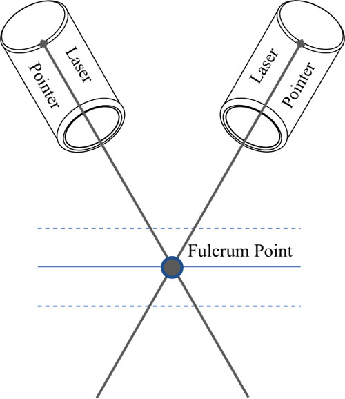
The driving system is a switchable function on the actuator and mechanism. The actuator connects to the grooved pulley, which rolls a wire by a clutch. Through the first function, called freehand, a surgeon can use instruments through the port by robot mechanism without electrical need. For the second function, called holder, the robot not only follows instrument manipulation by constraint mechanism but can be held in a certain position by the surgeon's control, thereby acting as a third hand. All actuators are not operated in this function. The third function, called teleoperation, is a combination of a clutch and actuator, which is a power transmission to robot end-effector, thus operated outside the working area [23, 24]. In this robot platform, there are two sides to MU-LapaRobot. The robot is controlled by a joystick in 4 directions. The driving system can be placed in a remote area (Fig. 6). The high torque actuators are used in the robot driving system.
The wire-driven system is used as the transmission of movement from actuators, hence making the end-effector lightweight, and requiring a low power to actuate it. Thereby providing strength points such as high stiffness, low friction, high strength, low weight, absence of backlash [25]. When the clutch is on, the rotation of the driving pulley is locked. Consequently, the motion of a surgical instrument is held in a certain position. When the pulley is moving, the cable trajectory along the pulley’s axis direction is changed. One end of the wire is collected when the driving pulley turns into a joint of translation. The number of turns will increase at one side of the driving pulley when it collects wire in the groove by robot movement. On the other hand, another side of the driving pulley, which fixes the other end of the cable rotates the same displacement along the alignment (Table 2). Consequently, the wire angle is changed while the driving pulley rotates forwards and backwards. For the driving system, the robot has 4 DOFs, which is motorized by 4 actuators and 4 electromagnetic micro clutch systems (Table 3). There are 3 features which include freehand, surgical tool holder, and teleoperation. The pulley is connected to the one side of the clutch, which attaches to the other side of the clutch. If the clutch gets electricity, the other side is connected to the actuator. The two terminals of cable are installed at the pulley by rolling cable in the groove with the number of turns depending on the rotation angle in each joint or length of translation of insertion. When the pulley turns in more, the angle of cable (n) will be changed. If the angle is high, it is possible for the cable to jump from the groove. Therefore, the system will fail to be controlled by teleoperation and surgical tool holder features.
| Function | Clutch | Actuator | |
|---|---|---|---|
| Freehand | => | Off | Off |
| Holder | => | On | Off |
| Teleoperation | => | On | On |
2.7. Passive Positioning Manipulator and Robot base
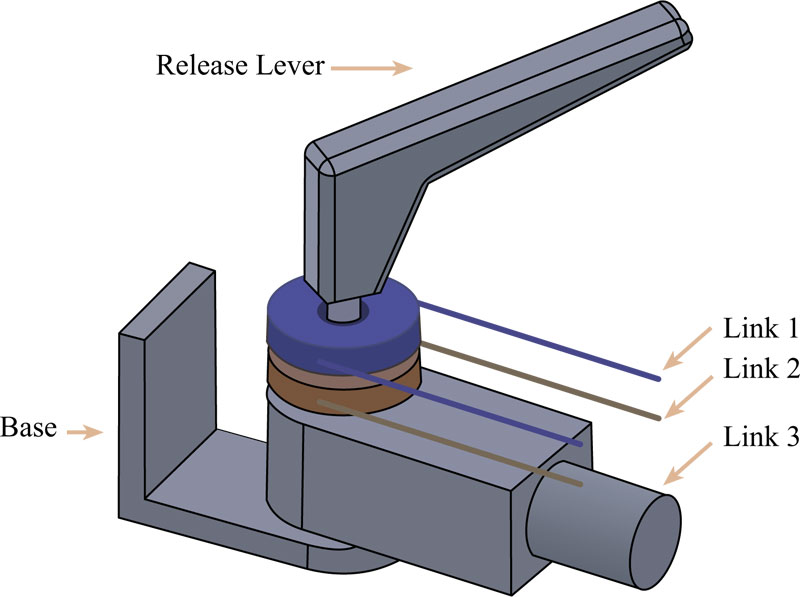
There are 2 passive arms on the robot base. An end-effector is attached at the end of the robot arm. The idea is a central locking arm designed planar which is able to move along the planar plane combined with vertical direction on the robot base using a wire-driven transmission. One step of adjustment stops or release an arm movement. In this mechanism, a release lever at the joint is adjusted manually. By turning the release lever, the friction force increases between pulleys that rolls on a wire and linkage surface. There are 3 linkages and 3 layers of the rotor under the release lever. Friction force will increase with compression force from the locking process (Fig. 7) so that all rotors and link 3 have more friction force on its contact surface. When the release lever is turned until its tight, all moveable parts will not be able to turn by an external force. On the other hand, all rotors freely rotate when there is less friction force on the surface. All joints can be rotated in 180 degrees.
The base of the Robot platform has 4 lockable wheels. The pole of the robot platform has a rectangular base in a vertical direction. It can be mounted with a robot arm or other equipment. The back of the platform has a box for computer units or store equipment. The adjustment of a lever is easy because of the weight balance in a pole. The weight balance can be adjusted by changing a weight bar inside a pole. This platform helps to carry all weight and easy to move.
3. EXPERIMENT
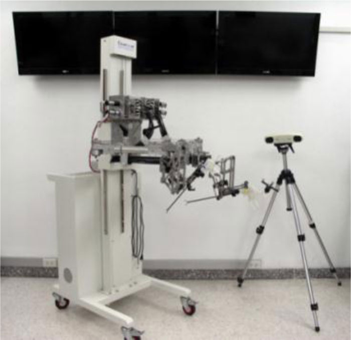
In the experiment, MU-LapaRobot was tested on its functions by using the measuring device. The NDI PolarisVicra Position Sensor Camera is used to test a position of a robot controlled by a computer. Polaris is an optical system that measures the 3D coordinate of passive markers and simulates the real pathway of the instrument. It can distinguish the shape of a marker by a pattern of reflector ball on the marker. The workspace of the robot is simulated from acquiring a 3D coordination from a sensor and transfer to calculation. An experiment tested the repeatability and accuracy of the robot to be 10 times at the same speed. The marker is attached to a moving part of the robot joint. An optical camera is located in the range of camera vision to detect an optical marker. The coordinate parameters are measured from a moving part. In order to record force-torque characteristics, F/T sensor ATi Nano25 was used for the measurement of 3 axes of forces (Fx, Fy, Fz), 3 axes of torque (Tx, Ty, Tz); orientation. The sensor was mounted onto a custom designed 3d printed holder with acting as a case for the surgical instrument.
| Degree of Freedom | Range (angle/ displacement, mm.) |
|---|---|
| #1 DOF | 160 degree |
| #2 DOF | 75 degree |
| #3 DOF | 160 degree |
| #4 DOF | 160 mm. |
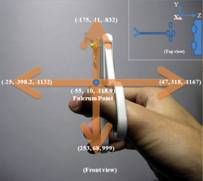
The surgical instrument is attached by a marker and is manipulated from up to down and left to right on a robot range of movement, as shown in Fig. (8). The simulation in this experiment only measures Joint 1 and Joint 2 to see how surgical instrument moves along a robot workspace. One stroke of insertion is about 15 cm, which is half of the long sleeve of a surgical instrument. The coordinates on the limitation of movement can be calculated to find the angle in each direction by Euclidean distance (11). The angle inside the triangle can be calculated by trigonometry (12).
 |
(5) |
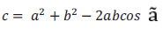 |
(6) |
Where, D denotes the distance between two coordinates, i denotes the number of 3D coordinates, ã denotes the angle opposite the side of length c between lengths b and a.
The coordination of marker, with respect to the fulcrum point of mechanism, generates a relationship of two directions in a cone shape. The angle at each point between Polaris and fulcrum point can be calculated. There are many data sets from Polaris Victra while a marker is moving. The simulation from manipulating a surgical instrument in the workspace shows the virtual environment of movement. Four perspective views of movement are shown in Fig. (9). The angles from top to bottom and left to the side are more than 60º. In this experiment, the surgical instrument is manipulated in two directions up to down and left to right to see the action through the incision point. The length of the insertion moves along the z-axis.
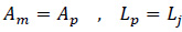
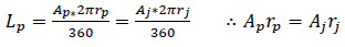
The long transmission may cause an error of manipulation. In the driving system, each actuator connects to the clutch, which connects to the groove pulley. Once a joint is rotated, the other joints remain the same. A clutch connects to the actuator and groove pulley to transmit a torque by wire, which travels to the joint. The angle of rotation in each joint is relative to the travel distance of the wire. The relationship between the angle of rotation and distance is in equation (8). In this experiment, the robot is tested about the position of the surgical instrument to which the marker from Polaris Victra is attached when it is rotated by the driving system. Next, the camera is adjusted to cover the range of view. The robot is controlled by using a microcontroller to command the angle movement.
 |
(7) |
 |
(8) |
Where, A denotes angle of rotation; L denotes wire length of rotation and m, p, j denote motor, pulley groove, and joint.
4. RESULTS AND DISCUSSION
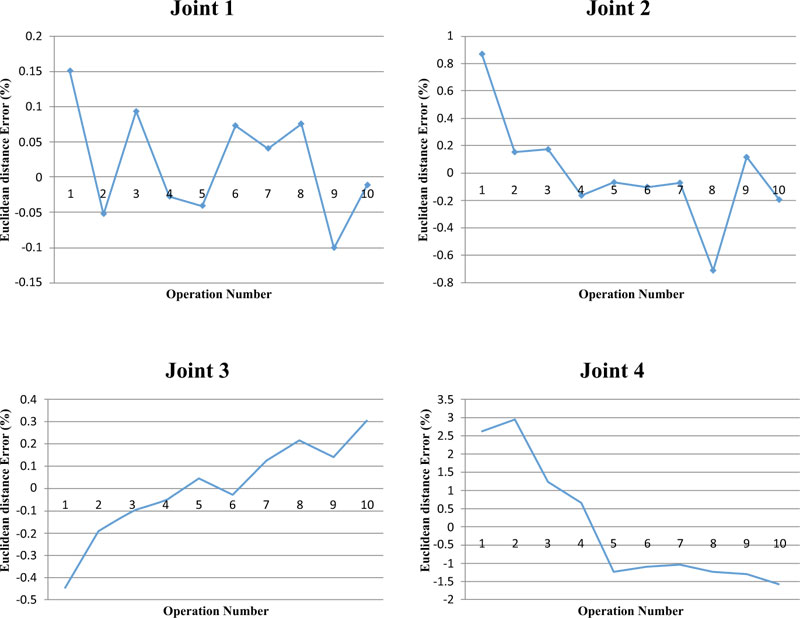
The results of (Fig. 10) show the errors. The result of joint 1(vertical joint axis or planar joint) is rotated at 80 degrees of joint angle and shows errors approximately 1 millimeter of each axis. Joint 2 rotates the robot end-effector at an angle of 50 degrees in each test. It has long displacement on X1 but the rest has few errors. Both joint 1 and joint 2 are a combination of axes which generate cone workspace (Fig. 11). Joint 3 which rotation angle of the test is 120 degree of the axis of the instrument shaft has a few errors about a millimeter in each axis similar to joint 1. Joint 4(translation joint) has a stroke of 15 cm length. A stroke of the test is 10 cm. It has long displacement on the X-axis and Y, Z also has some error. Two dots of laser pointer at the end-effector become one dot, represent the center of fulcrum point. If two dots laser pointer shows on the abdominal wall mean the height of the end-effector is too high or too close. (Fig. 12). In this step, the robot does not install with a surgical instrument. The modified surgical instrument is attached with a small adaptor on the instrument shaft using a standard trocar.
CONCLUSION
The design and development of cooperative robots are proposed for laparoscopic surgery. There are three main parts of this robot: first is the Active MU-LapaRobot with end-effector, about 1.5 kilograms (lightweight), second is the Passive Positioning Manipulator, which uses wire-driven transmission in structure. The manipulator is convenient for adjusting a position on the planar plane and positioning the entry point on the abdominal wall. And the third is the Robot Base, which is a mobile platform that can adjust the vertical length of the Passive Positioning Manipulator. These two parts are adjusted to position the entry point. The adjustment in vertical and horizontal planes is determined before Active MU-LapaRobot runs. The Active MU-LapaRobot, which has a mechanical constraint, works above the abdomen. The driving system is the power source that transfers it to the joint movement by the wire-driven method. There is 4 DOF for surgical tool manipulation with a semi-motorized system. The laser positioning helps to find the incision point on the abdominal wall. As the surgical tool holder functions, teleoperation and cooperation work when all clutches are turned on. (Fig. 10) shows that joints 1 and 3 have a low error in a millimeter because these joints need low torque, while joint 2 has some errors on one side of the movement. On joint 4, high errors happen due to the effect of Joint 2. Four joints are relative in joint movement. Consequently, the surgical instrument can be manipulated quite freely, but it still has a friction problem in the translation joint that will be solved in the future by improving the control system.
LIST OF ABBREVIATIONS
| MIS | = Minimally Invasive Surgery |
| MIRS | = Minimally Invasive Robotic Surgery |
| DWS | = Dexterous Workspace |
| EDWS | = Extended Dexterous Workspace |
ETHICS APPROVAL AND CONSENT TO PARTICIPATE
Not applicable.
HUMAN AND ANIMAL RIGHTS
No animals/humans were used in the studies that is the basis of this research.
CONSENT FOR PUBLICATION
Not applicable.
AVAILABILITY OF DATA AND MATERIALS
The authors confirm that the data supporting the findings of this research are available within the article.
FUNDING
This research is financially supported by the National Research University Funds through Mahidol University and Government Research Budget through Mahidol University (Grant No. 111-2558). Another fund resource was the Computer-Integrated Intelligent Medical System Project under the Thailand National Research University Grant through Mahidol University, Thailand.
CONFLICT OF INTEREST
The authors declare no conflict of interest, financial or otherwise.
ACKNOWLEDGEMENTS
The authors gratefully acknowledge the research support from the Center for Biomedical and Robotics Technology, Faculty of Engineering, Mahidol University, Thailand. Moreover, Sakol Nakdhamabhorn, Branesh M. Pillai, and BART LAB Researchers for their kind support.