All published articles of this journal are available on ScienceDirect.

Comparative Study of Femur Bone Having Different Boundary Conditions and Bone Structure Using Finite Element Method
Authors Info & Affiliations
Abstract
Background:
Femur bone is an important part in human which basically gives stability and support to carry out all day to day activities. It carries loads from upper body to lower abdomen.
Objective:
In this work, the femur having composite structure with cortical, cancellous and bone marrow cavity is bisected from condyle region with respect to 25%, 50% and 75% of its height. There is considerable difference in the region chosen for fixing all degrees of freedom in the analysis of femur.
Methods:
The CT scans are taken, and 3D model is developed using MIMICS. The developed model is used for static structural analysis by varying the load from 500N to 3000N.
Results:
The findings for 25% bisected femur model report difference in directional deformation less than 5% for loads 2000N and less. In the study comparing fully solid bone and the composite bone, the total deformation obtained for a complete solid bone was 3.5 mm which was 18.7% less than that determined for the composite bone.
Conclusion:
The standardization for fixing the bone is developed. And it is required to fix the distal end always with considering full femur bone.
1. INTRODUCTION
Femur bone is one of the important associate bones constituting the hip joint and is exposed to different forces during standing, walking, or running [1]. The comprehensive biomechanical properties of the cancellous bone of distal femur are generally accomplished through a series of mechanical tests, comprising of tensile test, compression test, torsion test, shear test, bending test and impact test [2, 3]. The accurate determination of biomechanical properties of bone is a precondition and is relevant especially for research related to the design and manufacture of artificial joint, rectification device, and implants [4]. The biomechanical properties obtained from the experimental studies are very sensitive to the test conditions and methods used [5]. Although there are many studies exploring the biomechanical properties of femur, the practical challenges in adopting these properties are the inconsistency in the experimental methods reported [6, 7]. The experimental models that involve the study of tensile or compressive loading for fracture analysis require securing the femur in a solidifying base such as plaster of paris or dental powder to avoid the deformation and destruction. The fixation of the specimens is the key to the success of the tensile test and torsion test [8]. This not only helps overcome the stress concentration but also obtain perfect specimens and good fixation effectiveness to ensure successful experiment result. In a study by Vitor M.M. Lopes et.al, 2017, the full femur was considered and it was fixed at 94mm from the condyle region [9]. Lorenzo Grassi et.al., 2016, validated the finite element models of human femora against experimental data from three cadaver femora. The femur was resected 55mm below the minor trochanter for the study [10]. In a comprehensive study by Chunjuan Du et al., 2006, 10 cancellous bone specimens were analysed for their mechanical properties. The length of the fixed part of specimen was 10 mm, and the width was 14.8-15.2 mm. The nominal length of the tensile part of specimen was 20 mm, and the height was 4.9-5.2 mm. The cancellous bone specimens for torsion test were processed to be cylindrical ones, whose length ranged from 46.4 mm to 49.8 mm.
In contrast to the experimental studies, Finite element analysis of femur has provided better insight into the stresses and displacement obtained for various loads acting on the femoral head [11, 12]. The mechanical behaviour of human femurs using FEM is made possible by conversion of the CT scan images into 3D CAD models [13-16]. Most studies involving FEM also adopted the experimental limitations of fixation and there exists considerable difference in modelling approach. J.H. Keyak 2001, used the nonlinear FE modelling of femur and estimated the proximal femoral fracture. A quarter from the top of femoral head section of femur was constrained by applying load to the femoral head [17]. Liang Peng et al., 2005, used the complete femur for single stance by fixing the condyle region [18]. In another study by Peter J. Laz et.al, 2007, the stress, strain and load transferred in human femur were evaluated by constraining the region just below the greater trochanter [19]. Enrico Schileo et al., 2008, used CT scans of cadaver femurs for modeling and fixed the distal end. Meanwhile, Nir Trabelsi et.al., 2009 developed the 3D models of femurs and constrained the femur shaft [20]. In another study, the hip joint contact force and adductor muscle force of a heterogeneous 154 mm long femur model was analyzed [21]. A study by J.H.Marangalou et al., 2012 used the micro CT of human femur having a length of 92mm and used this model to analyze the stress. The distal end and greater trochanter were constrained in the study [22]. Enrico Schileo et al., 2014, accomplished the FEM study by fixing 50% of bone from the condyle region [15]. Similarly, Ashwani Kumar et.al., 2014 considered the full femur bone for carrying out free vibration modes analysis of femur bone [23].
Another important disparity observed in the FEM analysis of femur bone was the composition of the bone structure [24]. Few studies have carried out a structural analysis using a fully solid bone. They have assumed the femur to have a single composition having the properties of cortical bone alone. The bone marrow cavity was neglected and analysis was performed to study the mechanical properties of femur subjected to various loads [25, 26]. Anatomically, the femur is composed of cortical and cancellous bone layers enclosing the femur cavity which hosts the bone marrow [27, 28].
The forces applied on the femoral head acts at an offset distance from the central axis. Consequently, the bending stresses are predominant, and distortion will be significant. The fixed support applied in FEM analysis will influence the bending stresses developed. Therefore, in this study, the femur bone was subjected by constraining various distal locations to ascertain the impact on the human femur using ANSYS 18. Also, a comparison is carried out between the composite bone and a fully solid bone to evaluate their differences. In the absence of standardization in practice, this study will demonstrate the importance of employing the correct boundary condition to capture the actual conditions.
2. MATERIAL AND METHODS
Anonymized male patient CT scans were obtained from Kasturba Medical College, Manipal for this study [Age of the patient was 36 years length of the femur was 461mm (Weight 76Kgs)]. Philips Brilliance 64 channel CT scanner was used to obtain the CT DICOM images with slice thickness 0.625mm. The 3D model of the femur was developed using MIMICS (Materialize, Leuven, Belgium) [29, 30]. Initially segmentation was carried out and with edit mask option the model was filtered to obtain a new geometry consisting exclusively of bone [31, 32]. In this study, two different bone models were compared. The first type was a composite femur (Model 1) having separate cancellous, cortical and bone marrow cavity [33, 34]. The second type named as Model 2 was a fully solid bone with the property of cortical bone alone. There was no distinction made between the various bone layers such as the cortical, cancellous and bone marrow cavity [33]. This was necessitated because few studies made use of a single bone structure in the analysis of femur [14, 31].
The following material properties were considered for the study as shown in Table 1. [35-37].
| Sl | Material Properties | Cortical Bone | Cancellous Bone |
|---|---|---|---|
| 1. | Young’s modulus | 17 GPa | 0.52 GPa |
| 2. | Density | 2 gm/cm3 | 1.08 gm/cm3 |
| 3. | Poisson’s ratio | 0.30 | 0.29 |
| 4. | Tensile strength | 130MPa | - |
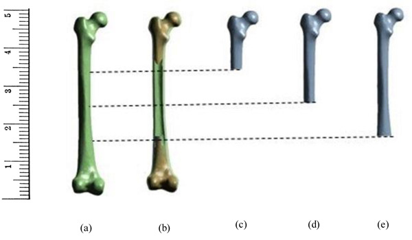
In the present study, the bone was assumed to be as linear isotropic material [32, 34, 38]. The analysis was carried out for single leg stance at different loads ranging from 1000N to 3000N. The load was applied from femoral head normal to its axis which was almost 4 times the body weight [12]. The distal end of the femur (condyle region) was constrained in accordance with the previous works [13, 20, 9, 33, 39]. In order to determine the effect of fixed support in the analysis of the femur, the bisection of the femur was carried out based on the constraints adopted in both experimental and numerical studies available in the literature. The fixed support employed in many studies was usually in the region 25% from the condyle section. Therefore, in this study, the femur was subdivided into 3 categories as 25% from condyle, 50% from condyle, and 75% condyle which is then compared with the primary model having fixed condyle region. Fig. (1) shows the femur and bisected bones used in the study.
The models were meshed using fine type meshing technique. The grid dependency study resulted in mesh count of 5,75,174 elements for the complete femur. The other models were bisected from the condyle region and therefore the elements were less than the complete solid femur.
3. RESULTS
3.1. Comparison of Fixed Support
The result of the present study closely matches to that available in the existing literature. The minor variations can be attributed to the differences in the femur length and other anatomical variations. The tabulated results are as shown in Table 2.
| Comparable Validation Parameters | Present Study | Available Literature |
|---|---|---|
| For 25% of femur length from femoral head (load applied 3000N) displacement in Z axis |
0.42mm | 0.4mm [4] |
| For 50% of femur length and fixed the bottom surface (the load applied 3000N) Total displacement |
5.7mm | 4.2mm [7] |
| For 75% of femur length from femoral head (load applied 1000N) Total displacement |
3.5mm | 3.3mm [11] |
| For 25% of femur length from femoral head (load applied 1000N) von Mises Stress |
17.5MPa | 17.49MPa [9] 19MPa [10] |
| For 75% of full length femur (load applied of 3000N) von Mises Stress |
63.017MPa | 57.17MPa [19] |
Fig. (2) shows the comparative findings between the full femur and the bisected femur. The results show the significance of bisected femur bone model in the evaluation of femur. There is a huge variation in results between the full-length femur and the bisected models.

Fig. (3) shows that distribution of maximum stresses on the mid-section of the femur bone. The mid section planes at which the maximum stresses are captured are identified by the horizontal dotted line shown in Fig. (6). The maximum stresses obtained was at the medullary region of the femur when the full-length femur was taken into account. The bisected models reported higher stresses in the neck region. These findings are similar to those presented in the literature [19].
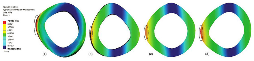
Table 3 shows the percentage change in the value obtained for directional deformation for the bisected model when compared to a full-length femur.
| Load | 25% Bisected from Lateral Condyle | 50% Bisected from Lateral Condyle | 75% Bisected from Lateral Condyle |
|---|---|---|---|
| 1000N | 4.75 | 27.71 | 66.26 |
| 2000N | 4.93 | 27.79 | 66.24 |
| 3000N | 6.83 | 27.76 | 66.23 |
3.2. Comparison of Solid Femur v/s Femur with Cortical, Cancellous and Bone Marrow Cavity
Another important disparity in the FEM analysis of Femur is with regards to the type of bone structure chosen. Several studies have utilized a fully solid bone structure having cortical bone properties without considering cortical, cancellous and bone marrow cavity in the FEM analysis [40-42]. Therefore, in this work, a comparative study of a composite bone structure (Model 1) and fully solid bone (Model 2) is carried out.
Fig. (4) shows the comparison of complete solid bone developed using only the cortical bone properties and the composite bone having independent properties of cortical, cancellous and bone marrow cavity. It can be noted that composite bone and complete solid bone behave differently. The directional deformation value determined for the complete solid bone was 0.35 mm and that observed for the composite bone structure was 0.41 mm for an applied load of 1000N. The total deformation obtained for a complete solid bone was 3.5 mm which was 18.7% less than that determined for the composite bone. Similarly, the von Mises stresses were underreported when the complete solid bone was taken into consideration. The findings were identical for any increase in applied loads considered. In general, the complete solid bone will result in lower values of stresses and deformation when compared with the composite bone structure. The composite bone structure represents the actual femur anatomy and therefore, FEM analysis should take into account the properties of individual layers that constitute the femur for accurate analysis.
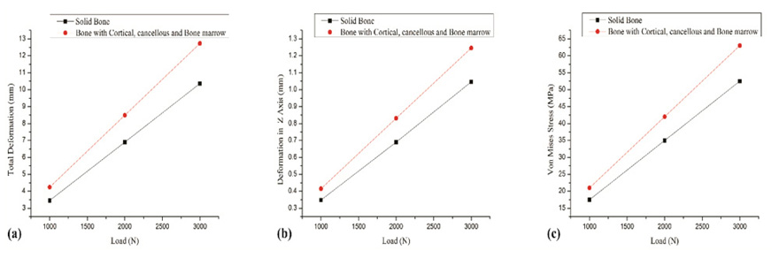
Fig. (5) represents the contour plot for total deformation for composite bone and fully solid bone structure. The differences between the 2 bone structures are clearly visible and are also reflected in the region of maximum deformation. The composite bone showcases high intensity of deformation at the femoral head and the greater trochanter region. However, when a fully solid bone structure is considered, the total deformation is limited to only a small area at the femoral head where the load is acting. This can be attributed to the absence of bone marrow cavity and cancellous bone in the analysis of fully solid bone.
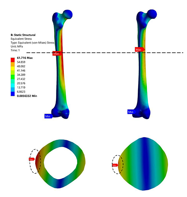
Fig. (6) represents the contour plot for distribution of von Mises stresses in the composite bone and the fully solid bone structure. It is evident from this study that bending stresses are predominant and is reflected in the concentration of maximum stresses in the medullary region of the femur. The findings are similar to most of the literature studied [33, 43, 44]. This is primarily because the load is applied on the femur head which is at an offset distance from the principle femur axis. The distribution of stresses is not very significant in the case of fully solid bone as can been seen in Fig. (3b). The fully solid bone is densely populated with a bone structure having properties of cortical bone and is capable of withstanding heavy loading. But this is not reflective of actual bone structure and therefore considering a fully solid bone is not desirable to evaluate its properties. Fig. (3c) and Fig. (3d) show a sectional view of the femur at an arbitrary height along the length of the femur. The results of stresses developed inside this section clearly articulate the difference in choosing a fully solid bone and a composite bone for FEM based analysis. In a fully solid bone, the stresses are well absorbed within the bone, whereas the effect of loading is significant in the composite bone. Experimental studies show that femur will fracture if the von Mises stress exceeds 114MPa [45] [46] [47]. Despite, the fully solid bone resulted in von Mises stresses to be much lesser than the fracture value reported in literature, it is not the representation of actual femur. This has implications in the design of implants and as a consequence, any study of femur and its implant should take into account its individual bone properties. Thus, considering complete solid bone will not provide the accurate reflection of its behaviour.

4. DISCUSSION
Most literature has unanimously considered the femoral head for application of load. But there is a considerable difference in the region chosen for fixing all degrees of freedom in the analysis of femur. This is particularly important in experimental studies that are carried out to determine the mechanical properties. There is lack of standardization and as a consequence, there is wide variability in the findings reported in literature. In this work, the femur having a composite structure with cortical, cancellous and bone marrow cavity is bisected from condyle region with respect to 25%, 50% and 75% of its height as shown in Fig. (1). The bisected models broadly fall in the range reported in the literature [9, 20, 21].
As the length of the femur reduces, the total deformation and directional deformation in Z-axis decrease. On the other hand, a significant increase in the value of von Mises stresses is reported for bisected femur bones. The directional deformation for 25% bisected femur was 0.42 mm for 3000N applied load. This was similar to the study by J.H. Keyak 2001 who used nonlinear FE modelling of femur to estimate the proximal femoral fracture [17]. [Enrico Schileo et al., 2008] trimmed the femur to include only the distal cement pot of femur as fixed support. The total displacement obtained in their work was 4.2 mm, whereas the present study reported a value of 5.72 mm on the application of 3000N [45]. In the present study, the bisected model was exactly 50% from the femoral head, whereas in the study reported by Enrico et al., bisection was in the vicinity of 50%. This is the reason for the large difference in the values reported for total deformation. Similar findings were reported for the experimental study carried out by Vitor M.M. Lopes et.al., 2017, where they constrained the model at 94mm above the condyle region. The total displacement obtained in their study was about 3.3mm for 1000N load [9]. In the present study, the total deformation reported was 3.458 mm for identical bisection of 75%.
In a study by [J.H.Marangalou et al., 2012] a load of 1000N was applied on the femoral head for a model considering only 25% of its original length. The value of maximum principle stress obtained in the study by Marangalou was around 19MPa which was almost the same at 20.71 MPa in the presence of identical conditions [22]. Similar stress values (17.49 MPa) were reported in the study by T. San Antonio et.al., 2012 when it was subjected to 1000N [21]. Whereas, in the study by Gillian E. Cook et al., 2017 von Mises stress obtained was 57.7MPa [38] for an implant inserted femur model constrained at 30% of its height from the condyle. In the present study, the stress obtained was 63.017MPa for 75% length of the femur at 3000N applied load. Fig. (3) shows that there is a significant difference in the location where the maximum stresses acts. In the analysis of full-length femur and 25% bisected femur, the maximum stresses were developed in the medullary region of the bone. This shows that the bending stresses are predominant in the femur analysis. This is because the load is applied on the femoral head which is at an offset distance from the principle axis of the bone. On the other hand, 50% and 75% bisected models reported maximum stress values near the fixed support. This is because in the heavily bisected bones, the bending moment is not predominantly influencing the behavior of the stress.
Table 3 shows the percentage change in the value obtained for directional deformation for the bisected model when compared to a full-length femur. It can be inferred from this study that for highly bisected models (50% and above), the difference in the result is very high. This has implications in conducting experimental studies involving femur. Most experimental studies considered only a quarter of the femur for analysis [14, 15, 22, 32]. The reason being, the need to secure the femur model during experiments. However, the findings of the present study clearly indicate large variations in the values of deformation and stress obtained. As a consequence, the experimental findings having highly bisected femur are therefore not reliable and require corrections. The tabulated findings for 25% bisected femur model report difference in directional deformation less than 5% for loads 2000N and less. Overall, the variation is less than 7% for 3000N applied loading. Thus, it can be concluded that the experimental models should have at least 75% of the femur length for reliable results. Consequently, only 25% of the model from the condyle region need to be secured during experiments.
CONCLUSION
In this work, the femur having a composite structure with cortical, cancellous and bone marrow cavity is bisected from the condyle region with respect to 25%, 50% and 75% of its height. The highly bisected models (50% and above), the difference in the directional deformation is greater than 27%. The findings for 25% bisected femur model report difference in directional deformation less than 5% for loads 2000N and less. Thus, it can be concluded that the experimental models should have at least 75% of the femur length for reliable results. Consequently, only 25% of the model from the condyle region need to be secured during experiments. For the study comparing the composite femur and completely solid femur, the total deformation obtained for a complete solid bone was 3.5mm which was 18.7% less than that determined for the composite bone. Similarly, the von Mises stresses were underreported when the complete solid bone was taken into consideration. The composite bone structure represents the actual femur anatomy and therefore, FEM analysis should take into account the properties of individual layers that constitute the femur for accurate analysis.
ETHICS APPROVAL AND CONSENT TO PARTICIPATE
Institutional ethical clearance is obtained by Kasturba Medical College, MAHE, Manipal, Karnataka, INDIA.
HUMAN AND ANIMAL RIGHTS
No animals/humans were used for studies that are the basis of this research.
CONSENT FOR PUBLICATION
Informed consent was obtained from all the participants.
CONFLICT OF INTEREST
The authors declare no conflict of interest, financial or otherwise. All the parts including research, manuscript and abstract are original and have not been presented in any form before.
ACKNOWLEDGEMENTS
The authors thank Radiology department, Kasturba Medical College, Manipal for providing CT scan data of the patients to carry out this work.