All published articles of this journal are available on ScienceDirect.

The Biomechanical Effect of Loading Speed on Metal-on-UHMWPE Contact Mechanics
Authors Info & Affiliations
Abstract
Ultra high molecular weight polyethylene (UHMWPE) is a material commonly used in total hip and knee joint replacements. Numerous studies have assessed the effect of its viscoelastic properties on phenomena such as creep, stress relaxation, and tensile stress. However, these investigations either use the complex 3D geometries of total hip and knee replacements or UHMWPE test objects on their own. No studies have directly measured the effect of vertical load application speed on the contact mechanics of a metal sphere indenting UHMWPE. To this end, a metal ball was used to apply vertical force to a series of UHMWPE flat plate specimens over a wide range of loading speeds, namely, 1, 20, 40, 60, 80, 100, and 120 mm/min. Pressure sensitive Fujifilm was placed at the interface to measure contact area. Experimental results showed that maximum contact force ranged from 3596 to 4520 N and was logarithmically related (R2=0.96) to loading speed. Average contact area ranged from 76.5 to 79.9 mm2 and was linearly related (R2=0.56) to loading speed. Average contact stress ranged from 45.1 to 58.2 MPa and was logarithmically related (R2=0.95) to loading speed. All UHMWPE specimens displayed a circular area of permanent surface damage, which did not disappear with time. This study has practical implications for understanding the contact mechanics of hip and knee replacements for a variety of activities of daily living.
1. INTRODUCTION
Osteoarthritis represents one of the most frequent causes of disability, pain, and joint dysfunction in adults [1]. This disorder potentially affects all synovial joints. It is character-rized by degeneration of articular cartilage and bone resulting in painful and restricted movement of the joint. The ultimate treatment for severe osteoarthritis is total joint replacement surgery [2]. Since artificial joints need to sufficiently withstand biological environments while under physiologic load, the need to improve the lifespan of joint prostheses is paramount, especially with the increasing life expectancy of the population [1].
Total hip and knee replacements have been successfully used for over 30 years and are the most common orthopaedic implant surgeries performed around the world, with over 250,000 hip and 500,000 knee replacement surgeries each year in North America [3]. A total hip replacement consists of femoral and acetabular components [4]. The femoral component is usually fabricated from a metallic alloy, such as cobalt-chrome (CoCr) or titanium (Ti) alloy. Ceramic femoral heads may be produced from alumina, zirconia-toughened alumina matrix composite, or oxidized zirconium composites. The acetabular cup is fixed to the pelvis and is made of ultra high molecular weight polyethylene (UHM-WPE), which can be either monoblock or modular [5,6]. A total knee replacement is comprised of a CoCr femoral component having a pair of condylar surfaces, a tibial component having a tibial platform fixed to the resected tibia, and a bearing component of UHMWPE interposed between the condylar surfaces and tibial platform [7,8].
Most current designs of joint replacements consist of metallic components articulating on UHMWPE components. UHMWPE is used due to its higher wear resistance compared to other polymers [9]. It has extremely long polymer chains, with a molecular weight numbering in the millions [8,9]. This results in a very tough material with the highest impact stress of any thermoplastic presently made [9]. Many aspects of artificial hip and knee replacements that use UHMWPE have been assessed in the past, such as contact stress [10-13], contact area [12-14], and wear [15,16]. Mechanical properties of UHMWPE itself have been characterized at different strain rates, including yield strength and creep [17,18]. The effects of rate-dependency on contact mechanics has been studied [17-19], while others have investigated the relationship between contact stress and area [20]. In addition, the effects of the viscoelastic nature of polyethylene on the contact stresses and load transmission in implanted knees have been determined [19]. However, the effect of compressive loading speed on metal-on-UHMWPE contact mechanics over a wide range of loading speeds has not been assessed.
The objective was to perform a preliminary experimental investigation on the effects of loading speed on UHMWPE behavior. Specifically, a series of identical UHMWPE test objects were subjected to compressive load by a metallic ball using a wide range of indenting speeds. This simulated in a rudimentary way the articulation of hip and knee replacements. This is the first study in the literature to do so. We hypothesized that contact force, area, and stress would be influenced by the viscoelastic nature of UHMWPE as loading speed increased.
2. METHODS
2.1. General Study Design
A metal ball was used to apply vertical force to a series of UHMWPE flat specimens over a wide range of loading speeds (Fig. 1). Force, area, and stress at the interface were obtained and correlated to loading speed. This approximated one aspect of metal-on-UHMWPE contact mechanics found in total hip and knee replacements during a variety of possible activities of daily living, such as walking, stair climbing, etc.
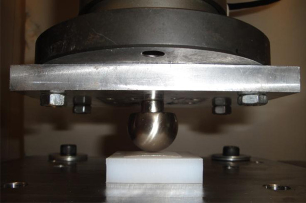
Test setup showing a spherical metal ball indenting an UHMWPE flat plate with a layer of Fujifilm placed in-between.
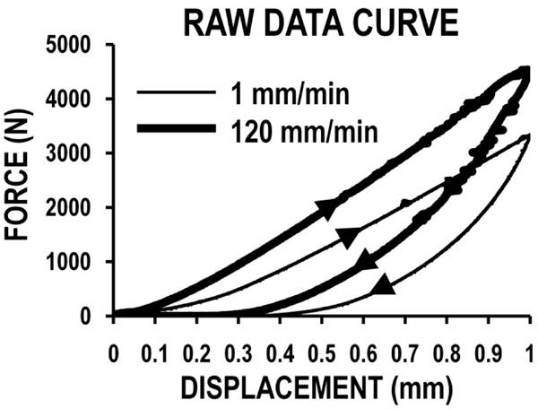
Raw force versus displacement curve showing typical patterns at low and high loading speeds. Other loading speeds demonstrated similar trends.
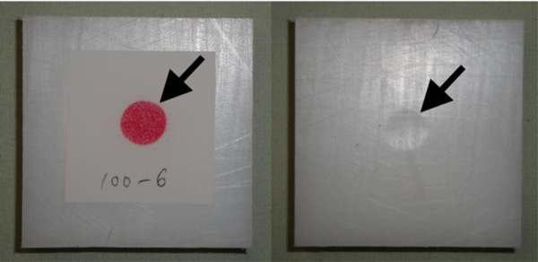
Raw contact area results for (left to right) a Fujifilm circular contact patch and the corresponding residual “button” resulting from permanent surface damage.
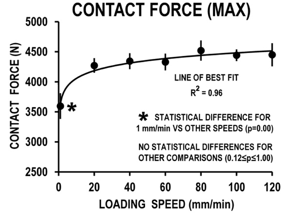
Maximum contact force versus loading speed. A logarithmic line of best fit produced excellent agreement with experimental data. Error bars are one standard deviation. p = statistical significance criterion; R2 = coefficient of determination.
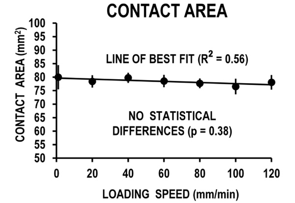
Average contact area versus loading speed. A straight line of best fit produced strong agreement with experimental data. Error bars are one standard deviation. p = statistical significance criterion; R2 = coefficient of determination.
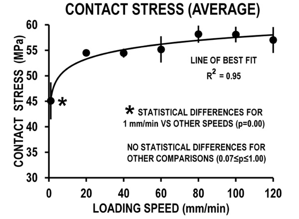
Average contact stress versus loading speed. A logarithmic line of best fit produced excellent agreement with experimental data. Error bars are one standard deviation. p = statistical significance criterion; R2 = coefficient of determination.
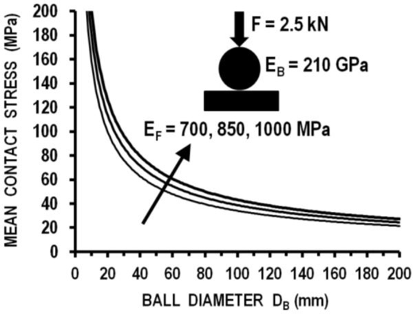
Hertzian theory computational results for mean contact stresses. CoCr ball-on-UHMWPE flat articulation was simulated over a range of clinically-used ball diameters and medical-grade UHMWPE elastic moduli. Load was applied by direct compression in a quasi-static manner, thus no effects of loading speed are considered. DB = ball diameter, EB = ball elastic modulus, EF = flat layer elastic modulus, and F = compressive force.
2.2. Test Setup
Using a band saw, a rectangular sheet of UHMWPE (Johnston Industrial Plastics, Toronto, ON, Canada) was cut into 42 identical squares of 50 mm x 50 mm x 12.7 mm size. UHMWPE material properties were 0.942 g/cm3 (density), 21.4 MPa (yield strength at 20°C), and 43.2 MPa (ultimate strength at 20°C). Each square was positioned onto the center of a metal baseplate. A double-sheet layer of pressure sensing ultra low Fujifilm (Fujifilm, Valhalla, NY, USA) was placed on top of the UHMWPE square. The Fujifilm had a 0.2 mm double-sheet thickness, a 0.2 MPa pressure sensing threshold, and an operating temperature range of 20-35°C. Directly over the center of the UHMWPE specimen was a smooth metal ball of 26 mm diameter, which is typical of the diameter of the CoCr femoral balls used in total hip implants and also for some aspects of the curvature of CoCr femoral components of typical total knee replacements [12,21]. The ball was bolted to a metal support plate and a mechanical tester’s load cell. The investigation was conducted at an ambient temperature of about 22°C.
2.3. Mechanical Tests
Tests were done using an Instron 8874 hydraulic mechanical tester (Instron Corp., Norwood, MA, USA). The load cell had a linear capacity of ±25 kN, a resolution of 0.1 N, and an accuracy of ±0.5%. The tester’s axial stiffness was 260 kN/mm which was many times higher than the anticipated stiffness of the polymer test specimens, eliminating the need to adjust the results to compensate for tester compliance. The mechanical tester was used to apply a vertical preload of 20 N through the metal ball to remove any “slack” in the test setup and UHMWPE specimen. Using displacement control, each UHMWPE specimen was loaded (and unloaded) to a 1 mm maximum vertical displacement with a speed of 1, 20, 40, 60, 80, 100, or 120 mm/min. Displacement control, rather than load control, was used so that the amount of vertical intentation was the same for all specimens. The 1 mm maximum displacement was used to generate representative physiological lower limb joint forces, such as hip joint loads which can range from 1500 to 6500 N for a variety of activities [22]. The total number of mechanical tests performed was 7 loading speeds x 6 UHMWPE specimens = 42.
2.4. Data Collection and Analysis
All data were collected using dedicated Instron software at a sampling rate of 1 kHz, i.e. at 0.001 s intervals. “Contact force” was defined as the maximum force identified from the force versus displacement graphs generated during each mechanical test. “Contact area” was defined as the total surface area engaged at the metal-on-UHMWPE interface as measured by Fujifilm, which was scanned in bitmap format at a resolution of 1200 dpi (dots per inch, or pixels per inch) and digitally stored. Image analysis was then done with SigmaScan software (Jandel Scientific, San Rafael, CA, USA), which was used to trace the boundary of each contact patch to obtain a contact area measured in pixels2 units, which was converted to mm2 units. “Contact stress” was finally computed for each mechanical test result by dividing contact force by contact area, which represented the average stress over the entire interfacial area engaged.
2.5. Statistical Analysis
Using SPSS statistical software (SPSS Inc. Chicago, IL. USA), one-way analyses of variance (ANOVA) were performed to detect differences between loading speeds for contact force, area, and stress. Tukey’s honestly significant difference was used if any post hoc comparisons were necessary. Significance was set at p<0.05. The coefficient of determination R2 was used to determine the agreement of experimental data with a theoretical line of best fit for graphs of contact force, area, and stress versus loading speed. A two-tailed post hoc power analysis was done to determine if there were enough specimens per group to detect all statistical differences that may have been actually present, i.e. avoiding type II statistical error.
3. RESULTS
3.1. Raw Force versus Displacement Graphs
Force versus displacement graphs for the lowest and highest speeds are shown (Fig. 2). Regardless of loading speed, non-linear behavior was observed during both the load application and load removal phases of the loading event. There was an associated energy loss indicated by the substantially reduced forces generated during load removal, i.e. hysteresis.
3.2. Fujifilm Measurements
Fujifilm data and residual surface damage are shown (Fig. 3). Fujifilm sheets yielded a well-defined circular area at the center of each specimen, which is consistent with the sphere-on-flat interface geometries used. UHMWPE specimens showed a circular area of permanent surface damage, which did not recover to its original condition.
3.3. Contact Force
Contact force versus loading speed results are shown (Fig. 4). Experimental values ranged from an average of 3596 to 4520 N and were well-described by a theoretical logarithmic line of best fit with an agreement of R2=0.96. The line of best fit showed a 25% increase in contact force over the entire loading speed range. However, no statistically significant differences were noted for any pairwise compa-risons of experimental contact force between loading speeds (0.12≤p≤1.00), except for 1 mm/min versus all other loading speeds (p=0.00).
3.4. Contact Area
Contact area versus loading speed results are shown (Fig. 5). Experimental data ranged from an average of 76.5 to 79.9 mm2 and were only moderately predicted by a theoretical straight line of best fit with an agreement of R2=0.56. The line of best fit illustrated a nominal 2.5% decrease in contact area with increased loading speed. However, there were no statistically significant differences for any pairwise comparisons of experimental contact area between loading speeds (p=0.38). Thus, it was appropriate to compute a combined average contact area for the entire loading speed range of 78.4 mm2.
3.5. Contact Stress
Contact stress versus loading speed results are shown (Fig. 6). Experimental values ranged from an average of 45.1 to 58.2 MPa and were well-described by a theoretical logarithmic line of best fit with an agreement of R2=0.95. The line of best fit showed a 31% increase in contact stress over the entire loading speed range. However, no statistical differences were detected for any pairwise comparisons of experimental contact stress between loading speeds (0.07≤p≤1.00), except for 1 mm/min versus all other loading speeds (p=0.00).
3.6. Statistical Power Analysis
Post hoc power calculations yielded averages of 52% (contact force), 20% (contact area), and 64% (contact stress), showing the study design was underpowered to detect all statistical differences that may have been present. A good study design is often considered to be 80% or higher. However, computations also showed that 5800 (contact force), 4500 (contact area), and 10,500 (contact stress) UHMWPE specimens per loading speed group would have been required to boost the power to 80%, which would have been unrealistic practically.
4. DISCUSSION
4.1. General Findings
The results illustrated the speed dependency of UHMWPE material. An increase in contact force and a decrease in contact area were related to a rise in loading speed. Increased contact stress was produced by either increased load or decreased contact area. The shape of contact areas themselves remains circular and symmetric despite changes in loading speed. This preliminary study is the first to examine the effect of vertical loading speed on the contact mechanics of a metal ball indenting a UHMWPE flat plate.
4.2. Comparison to Prior Studies
The contact mechanics of human or artificial joints have been studied previously at different flexion angles, load regimes, and temperatures. A comparison of present results with previous studies shows several things.
Our contact areas ranged from 76.5 to 79.9 mm2 and were much smaller than previous investigations for loads up to 2.1 kN (64.5 to 200 mm2) [13,17,18]. Similarly, a study of tibio-femoral dynamic loading and different loading rates reported 200 to 385 mm2 as the size of contact area [23].
Our Fujifilm sheets yielded a well-defined circular area on each UHMWPE specimen. Szivek et al. reported that contact areas varied from line-shaped to bilateral circular or elliptical shapes [10]. Manley and coworkers showed that among total knee replacements, such as the Miller/Galante, P.C.A. Modular, P.F.C., and the Natural Knee, only Ominfit exhibited symmetric contact areas [12]. Others had asymmetric contact areas which became more asymmetrical in malalignment [12]. Contact geometries can become more circular at higher temperatures [11].
Our average contact stress ranged from 45.1 to 58.2 MPa, which increased logarithmically with loading speed. This agrees with a previous study on UHMWPE that found a considerable increase in yield strength by increasing the strain rate [17]. It has also been reported that flexion angle and temperature influence average contact stress, increasing the values from 12 to 35 MPa [10,11]. Manley et al. [12] tested total knee replacements at two flexion angles and reported a maximum of 33 MPa mean stress on the UHMWPE component. Moreover, the maximum yield strength (less than 35 MPa) in other studies is lower than the current contact stress [10-12].
Any differences with our study can be accounted for by variations in methodology, such as loading levels, loading speeds, Fujifilm pressure sensitivity range, temperature, geometry, UHMWPE grade used, etc., as described below.
First, Szivek et al. [10,11] and Manley et al. [12] laterally constrained their tibial inserts by putting them into blocks. Zdero et al. [13] loaded the tibial components (without their metal trays) against a semi-rigid UHMWPE support plate and allowed them to self-align during loading. However, in the present study, a metal ball bolted to a metal support plate and a mechanical tester’s load cell was used to apply vertical force to a series of UHMWPE flat specimens that were resting freely on a metal baseplate and that were not constrained laterally.
Second, Szivek et al. [10,11] used a type of Fujifilm with a minimum sensitivity of 9.8 MPa. Manley et al. [12] did not report the pressure sensitivity range of Fujifilm grade used. The present study used an ultra low grade film with a low 0.2 MPa threshold.
Third, in our study, an impact force was applied to UHMWPE specimens, similar to Rullkoether et al. [17,18]. Other studies were carried out on total knee replacements with highly complex 3D geometry [10-12]. Moreover, Yeow et al. used hind legs obtained from pigs as specimens [24].
Finally, our study was done at an ambient temperature of about 22°C. However, polyethylene insert temperatures affect the accuracy of the measurements collected in modeling in vivo stresses [11]. Temperatures as high as 55°C have been measured during simulated in-vivo hip articulation [11]. Although it is likely that this is higher than the temperature in the tibial insert of an artificial knee, the 55°C test provided a third temperature point to allow assessment of changes in contact point with temperature. Since it is unlikely that temperatures at the tibial insert exceed body temperature, testing implants at 37°C provides a more clinically relevant scenario of implant response than did testing at room temperature at present.
4.3. Clinical and Biomechanical Implications
The lowest value of contact stress in the current investigation was about 45 MPa, which occurred for the lowest loading speed of only 1 mm/min. Since the plastic yield point for UHMWPE has been estimated to be 10 to 15 MPa [25], this suggests that even extremely slow loading speeds may cause permanent damage to the surface of the polymer inserts of total hip and knee replacements. This may be problematic for artificial joint implants that have low congruency and which produce small contact areas and high contact stresses, such as P.C.A. Modular, Press-fit condylar (P.F.C.), and Intermedics Orthopaedics implants [12].
Average contact stress currently increased by 31% over the 1 to 120 mm/min loading speed range tested. If a similar relationship were true for higher speeds more representative of physiological activities and injuries, the ultimate failure stress of UHMWPE would likely be reached at a lower vertical loading speed. This finding is consistent with the common clinical practice of discouraging joint replacement patients from engaging in high impact activities, such as skiing, jumping, dancing, etc.
The stress gradient at the outskirts of the contact region affects the amount of contact area underestimation and contact stress overestimation by Fujifilm. Because Fujifilm, like every technique, is influenced by the gap between the mating parts due to its limited pressure sensitivity and spatial resolution, bounding the contact area solution using several methods rather than with any single technique is recommended [13]. For instance, Zdero et al. used both Fujifilm and ultrasound to measure the contact areas of total knee replacements and suggested that the true value may be somewhere between those measured by the two methods [13].
Hertzian contact theory can illuminate present data by predicting stresses for a range of metal ball sizes and UHMWPE elastic moduli typical of total hip and knee replacements. First, consider the current metal ball-on-flat geometry undergoing direct compressive loading, as an initial “proof of principle”. Second, let us utilize a range of metal ball sizes typical of the curvatures of the CoCr femoral component of clinically-used total hip and knee replacements (i.e. diameter = 20 to 200 mm) [12,21]. Third, let us also incorporate elastic modulus (E) and Poisson’s ratio (P) values typical of medical-grade CoCr (E = 210 GPa, P=0.31) [26] and UHMWPE (i.e. E ≈ 0.7 to 1.0 GPa, P=0.4) [26-28]. Fourth, assume that a fixed compressive load of 2.5 kN is applied, which for an 80 kg person represents about 3 to 4 x body weight and is the typical peak force for hip and knee joints during walking [29]. Fifth, it should be noted that classic Hertzian contact formulas do not account for loading speed, thus, a quasi-static load application shall be assumed. Sixth, the Hertzian contact formula for this scenario can be expressed as,
where F = compressive force, DB = ball diameter, PB, PF = ball and flat Poisson’s ratio, and EB, EF = ball and flat elastic modulus [30]. Consequently, computations yield a non-linear relationship between mean contact stress vs. ball diameter that is affected by UHMWPE elastic modulus (Fig. 7). Based on the current experimental results (Fig. 6), an increase in loading speed would likely increase the computed stress levels from Hertzian theory (Fig. 7), but only up to a certain loading speed, beyond which the stress values may reach a steady-state. Certainly, the stress magnitudes computed would be different for the complex 3D geometries of actual total hip and knee implants, but the general trends would likely be maintained. These theoretical Hertzian calculations would need to be verified experimentally in a future work.
4.4. Addressing Possible Limitations
Fujifilm only gave a colored stain for pressures above the minimum threshold for the grade of film used [31]. Thus, Fujifilm grades with low pressure thresholds should be used for maximal detection of contact area. Even at a low minimum pressure threshold of 0.2 MPa as used presently, Fujifilm likely underestimated the contact area and, thereby, overestimated the average contact stress measured.
Fujifilm’s 0.2 mm thickness may interfere with proper mating of two bodies, since it increases the distance between components and leads to lower component congruency and smaller contact area [32]. As the distance between contact points become smaller, the results should become more accurate.
Fujifilm can “crinkle” or “jam” at the periphery of a contact area [13]. The consequence can be missing information from the contact patches, thereby greatly underestimating the actual contact area. However, this is only a serious problem for mating bodies with highly complex 3D geometries and not for simple ball-on-flat interfaces as used presently.
Calculations of contact stress during testing based on Hertzian ball-on-flat contact mechanics are more accurate for static loads [33]. For dynamic testing, as done presently, the stress calculated represents an approximation of the actual initial stress only because, as the material is subjected to damage, the ball-on-flat analogy becomes increasingly less valid [33].
The loading speed range in our study was limited to 1 to 120 mm/min as simply a proof of principle. This may not be representative of the real-life physiological loads during a full spectrum of normal activities of daily living or injury processes in artificial knee (80 +/- 10 m/min) or hip (70 +/- 10 m/min) replacements [34,35]. However, since the current force and area data plateaued for speeds beyond 20 mm/min, it is expected that higher real-life physiological speeds would not have affected current values.
Medical grade UHMWPE in modern implants is sterilized by gamma irradiation to enhance molecular cross-linking, thus affecting mechanical properties. Also, the medical grade UHMWPE in implants is heat treated in order to remove free radicals, which can interact with absorbed oxygen and lead to delamination of the outer surface. These effects were not evaluated using the present industrial grade UHMWPE.
For load bearing implant applications, and from the perspective of joint tribology, other parameters may also be important [36]. These include surface roughness, type of lubricant, lubrication modes, asperity-to-asperity contact prior to continuum contact, interfacial geometry, etc. Moreover, stress distribution across the contact area, through the material, and on the underside of the UHMWPE may give some further insights into the rate dependence of the material. These are important variables which affect the contact mechanics and material behavior of metal-on-UHMPWE articulation. These items were beyond the scope of our modest preliminary investigation, but should be considered in future investigations as the next logical steps in more realistically mimicking artificial joint conditions.
We also acknowledge the need for future experimental and/or computational studies to assess loading speed effects using the more complex 3D motions and geometries typical of total hip and knee replacements. Initially, such work could use simple geometries (e.g. ball-on-flat, cylinder-on-flat, etc.) to assess the effects of loading speed on pure sliding, pure rolling, and/or pure torsional motion at the articulating interface [37,38]. Afterwards, once basic behavior has been initially determined using the simple geometries, the more complex geometries of actual total hip and knee replacements could be tested using joint simulators to determine loading speed effects [39,40]. It is anticipated that when actual total hip and knee replacements produce more (or less) conforming articulations (i.e. geometric matching of the CoCr-on-UHMWPE interface) than the ball-on-flat currently used, the resulting contact areas will be larger (or smaller) than those presently measured and, thus, the mean stresses will be smaller (or larger). For instance, Manley et al. used a 669 N compressive load on a series of 11 different commercial total knee replacements in 90° of flexion and found that mean contact stresses varied from 10 MPa (most conforming) to 33 MPa (least conforming) [12].
Post hoc power analysis showed that the study would have required at least 10,500 specimens to bring all the power values above 80% for a good study design. Consequently, although the outcomes for force and stress were very strong vs. loading speed (R2≥0.95), the contact area results were only moderate in this regard (R2=0.56). Even so, contact area data only dropped by 2.5% over the full loading speed range examined, thus any estimates of contact area made using the line of best fit may not be particularly sensitive to loading speed.
CONCLUSION
A clear dependency of UHMWPE material on loading speed was observed. A rise in contact force and a drop in contact area were highly related to an increased loading speed. Increased contact stress was created by either a rise in load or drop in contact area. The geometry of the contact areas remained circular and symmetric with loading speed. This is the first study in the literature which has examined the effect of loading speed on the contact mechanics of a metal ball indenting a UHMWPE flat plate. As such, any shortcomings of this study stem from the “proof of principle” nature of this preliminary investigation. However, the essential findings of the study can now be expanded upon by future experimental and/or computational models, which account for more realistic 3D geometries found in clinically-used hip and knee implants.
FINANCIAL SUPPORT
No external funding was associated with this study.
CONFLICT OF INTEREST
There are no conflicts of interest for any authors.
ACKNOWLEDGEMENTS
Declared none.