All published articles of this journal are available on ScienceDirect.

Wireless Coexistence and EMC of Bluetooth and 802.11b Devices in Controlled Laboratory Settings
Abstract
This paper presents experimental testing that has been performed on wireless communication devices as victims of electromagnetic interference (EMI). Wireless victims included universal serial bus (USB) network adapters and personal digital assistants (PDAs) equipped with IEEE 802.11b and Bluetooth technologies. The experimental data in this paper was gathered in an anechoic chamber and a gigahertz transverse electromagnetic (GTEM) cell to ensure reliable and repeatable results. This testing includes: Electromagnetic compatibility (EMC) testing performed in accordance with IEC 60601-1-2, an in-band sweep of EMC testing, and coexistence testing. The tests in this study show that a Bluetooth communication was able to coexist with other Bluetooth devices with no decrease in throughput and no communication breakdowns. However, testing revealed a significant decrease in throughput and increase in communication breakdowns when an 802.11b source is near an 802.11b victim. In a hospital setting decreased throughput and communication breakdowns can cause wireless medical devices to fail. It is therefore vital to have an understanding of the effect EMI can have on wireless communication devices.
INTRODUCTION
Wireless in Healthcare
Striving to stay on the leading edge of technology, hospitals have entered the relatively new world of wireless communication. Hospitals are already using Wireless Medical Telemetry Service (WMTS) which operates on three frequency bands, monitoring vital human statistics. Now hospitals are beginning to implement various wireless local area networks (WLAN) and wireless personal area networks (WPAN). Whether or not different wireless technologies behave properly around each other needs to be addressed and is topic of this paper.
Infrastructures of IEEE 802.11b access points have been designed and strategically placed within hospital corridors and rooms. These access points allow roaming doctors and nurses to connect to a centralized network using a personal digital assistant (PDA), notebook computer, and more recently smart phones. Another emerging technology used in hospitals is Bluetooth (IEEE 802.15.1) which has shorter range and uses less power than 802.11b. Besides communicating with PDAs, smart phones, and notebook computers, 802.11 and Bluetooth technologies are being designed into wireless operating rooms and medical devices. The use of this wireless technology can provide many benefits including device mobility, providing doctors and nurses with portable and uninterrupted access to patients health records and present medical status, and clearing up space in an otherwise cluttered hospital. The use of this technology also has a number of drawbacks. Some of the drawbacks include the need for security of patient records, interference from intentional and unintentional radiofrequency (RF) emitters, and the question of constant dependability of the wireless signals. Implications for transmission slowdown or failure may be inconvenient when you are downloading a song or video, but when you are counting on diagnostic decision making from a medical device it can be life-critical. However, due to the tremendous potential created by these technologies, wireless in healthcare is here to stay.
Overview of ISM Band & Technologies
The 2.4 GHz ISM (Industrial Scientific-Medical) band (2400 MHz – 2483.5 MHz) is a commonly used unlicensed frequency band where both Bluetooth and 802.11b reside. Due to the fact that any manufacturer can use this space and because of the low cost of both 802.11b and Bluetooth, the 2.4 GHz ISM band is crowded and susceptible to interference.
802.11b is a wireless communication system designed to create WLANs. There are many different modulation techniques that 802.11b uses: binary phase shift keying (BPSK) for 1 Mbps (mega-bits per second), quadrature phase shift keying (QPSK) for 2 Mbps and complementary code keying (CCK) for 5.5 and 11 Mbps. If the user does not specifically choose the data rate, then it changes automatically upon signal strength and interference. The data rate will be lowered in the presence of low signal strength or high interference and will return to a higher rate when the interference is no longer present. The maximum output power of 802.11b is 1 W and has a range up to 100 meters. It uses DSSS (Direct Sequence Spread Spectrum) and each operating channel has a bandwidth of 22 MHz. There are 11 operating channels in the North American band (2400-2472 MHz), including three non-overlapping channels (channels 1, 6, and 11).
Bluetooth is a wireless communications system that is designed to operate in short-range WPAN. Typically Bluetooth has a maximum output power of 2.5 mW with a range up to 10 meters (Class 2 Bluetooth). However increasing the output power to 100 mW (Class 1 device) can increase the range to 100 meters. Bluetooth’s transfer rate is limited to 1 Mbps. Bluetooth channels are 1 MHz wide and use a pseudo-random hopping sequence to jump through frequencies from 2402 MHz to 2480 MHz using FHSS (Frequency Hop Spread Spectrum) at a rate of 1600 hops per second.
Literature Search
There are numerous references examining the coexistence issues that can occur between the two most common wireless communication technologies in the ISM band: 802.11b and Bluetooth. These papers [1-8] discuss how 802.11b and Bluetooth interfere with each other, but not how they respond to amplitude modulated (AM) signals encountered during electromagnetic compatibility (EMC) testing. Some of these publications [9] and [10] make recommendations on which technology is best used in hospital settings where life-supporting electronic devices may be present. These studies [1-8] go into detail about frequency hopping patterns, modulation techniques, media access control (MAC), and techniques for improving coexistence problems. The majority of these reports [3-8] have used computer simulation tools or numerical calculations to analyze these networks. Networks change frequently and it is unreasonable to experimentally test for all of these changes. Computer simulation tools are useful to solve coexistence issues because of their flexibility. However it is unclear how any of these simulation tools have been validated using real-life systems in experimental settings. Depending on the simulations and investigators, contradictory results were found, even in the most basic situations. One common example is the adjustment of transfer rates. In simulations measuring throughput of 802.11b in the presence of Bluetooth interference Keller [7] shows that higher throughput is achieved with the fragmentation of packets. The reasoning behind this is the faster a packet is transferred, the less chance it has for collision. Contrary to this Jo and Jayant [6] state that from their calculations the throughput (during times of Bluetooth interference) degrades the same, regardless of 802.11b data rates. Controlled, repeatable experimental results are needed in order to validate these simulations.
Experiments
This paper will discuss experiments that were performed in controlled laboratory settings. The findings of our experiments can be used to verify published computer simulation results, and allow readers to make reasonable decisions on the use of wireless technologies in the real world, including hospital settings. Data integrity was tested for several wireless communication links. The communication link was tested for three parameters: breakdown, data integrity, and throughput during exposure to various external sources. These sources included Bluetooth, 802.11b, and AM signals. The communications link’s electromagnetic field strength (emissions) was measured from several wireless devices.
GTEM TESTING
Devices
The Bluetooth victim link testing used two Hewlett Packard iPAQ HP5455 PDAs. Custom bluetooth software, residing on the PDA, was used to transfer files and monitor the communication link. The software takes advantage of a Widcomm library (Broadcom Corporation) that allows tracking of individual packets at both the receiving and transmitting PDAs. For each packet a time stamp and a MD5 code were recorded. A MD5 hashing algorithm creates a 128 bit code. This code is unique to the data used in the algorithm. The code can be compared, before and after transmission, and if the two codes are the same, the data is the same. This software allowed easy tracking of both throughput and data integrity.
The 802.11b victim link testing used two different devices. The receiving victim was a Toshiba E755 PDA and the transmitter was a Dell Lattitude D400 notebook with a Linksys WPC55AG 802.11 wireless adapter. Because 802.11b custom test software was not available for PDAs, two different devices were needed and the transfer mechanism was a Microsoft Windows copy command. Timing was captured with a stopwatch by visually watching the file transfer process. Data Integrity was checked at the file level by running a MD5 algorithm before and after transmission.
Both the Bluetooth and 802.11 victim links are operating in adhoc mode. In adhoc mode the devices are connected directly with each other without the use of an access point.
Setup
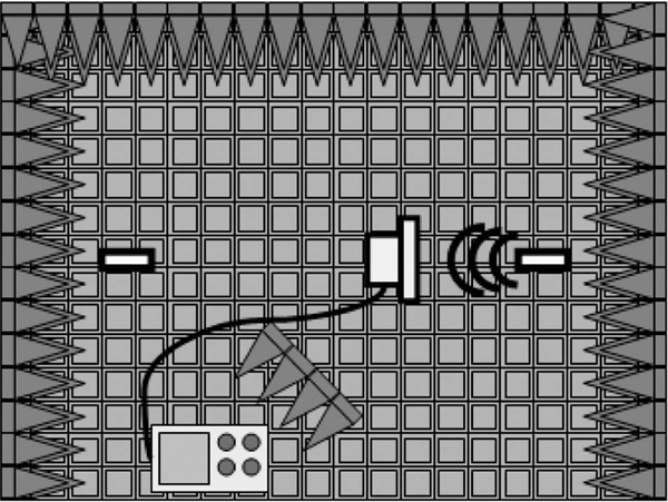
The victim link was placed inside of an EMCO 5317 GTEM (gigahertz transverse electromagnetic) cell with outer dimensions 7.7 x 4.1 x 3.1 meters (Fig. 1). A GTEM cell is a TEM (transverse electromagnetic) cell that operates up to several gigahertz. It is used as an EMC testing chamber that allows exposing objects to controlled electromagnetic fields. Linearly polarized electric fields are created when RF signals are introduced inside the GTEM. The placement of the victim link inside the GTEM is not trivial. Usually there is one device that is placed inside the GTEM, then signals are introduced, and then data from the exposed device is recorded. Since the test was on a communication link, both the transmitter and receiver needed to be inside of the GTEM. The receiver was chosen to be the test subject because preliminary tests revealed the majority of interference problems were seen when the receiver, and not the transmitter, was exposed. The small end of the GTEM has a higher electric field due to the low separation distances between the flat inner conductor (septum) and floor. Therefore the receiver was placed in the smaller end of the GTEM (see Fig. 1) to be exposed to the higher electric field. The victim transmitter position received less than 20% of the field strength seen by the receiver. Both devices were placed in the middle (vertically) between the floor and the septum (Fig. 1) for homogeneity of the field. The receiver’s antenna was placed to be parallel to the vertically polarized interfering field, thus giving a worst-case situation. To produce interfering signals an Aeroflex IFR 3416 (250kHz-6GHz) Vector Signal Generator was used with one of three different amplifiers: an Amplifier Research Model 10W1000 (1-1000 MHz), a Hughes TWT Model 8020H (1-2 GHz), and a Logimetrics Model A310/S-618 (2-4 GHz). The electric field strengths were measured with an ETS-Lindgren Holaday Isotropic Electric Field Probe (model HI-6005). Prior to victim link testing, the probe was placed in the same location as the victim receiver would be. The field strengths were then mapped as a function of input power using a Hewlett Packard HP438A power meter. This input power was used during the actual victim link testing.
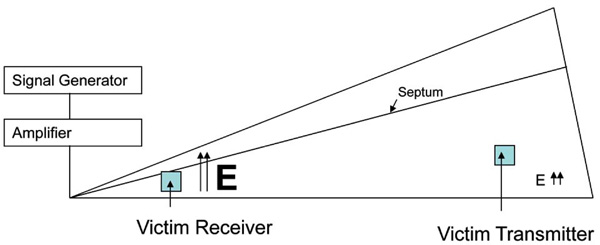
Test setup inside of GTEM cell. The victim receiver is placed at the smaller end with large E-Field and the victim transmitter is placed at the larger end with relatively small E-Field (the victim transmitter position received only 20% of the field strength seen by the receiver).
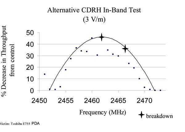
GTEM results (and best fit curve) from Alternative CDRH In-Band Test in terms of percent decrease in throughput. Victim link at channel 11 (center frequency 2462 MHz).
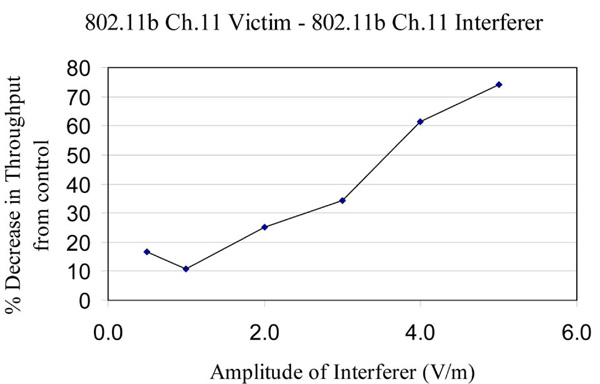
GTEM results from 802.11b Ch.11 victim and 802.11b Ch.11 source (interferer) in terms of percent decrease in throughput from control case (case with no interference).
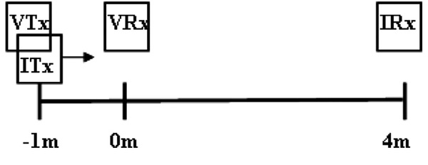
Top view of Anechoic Chamber setup. VTx stands for the victim link’s transmitter, VRx for the victim link’s receiver, ITx for the interfering link’s transmitter, and IRx for the interfering link’s receiver. ITx is moved from (-1 m) through VRx (0 m) up to (3.5 m).
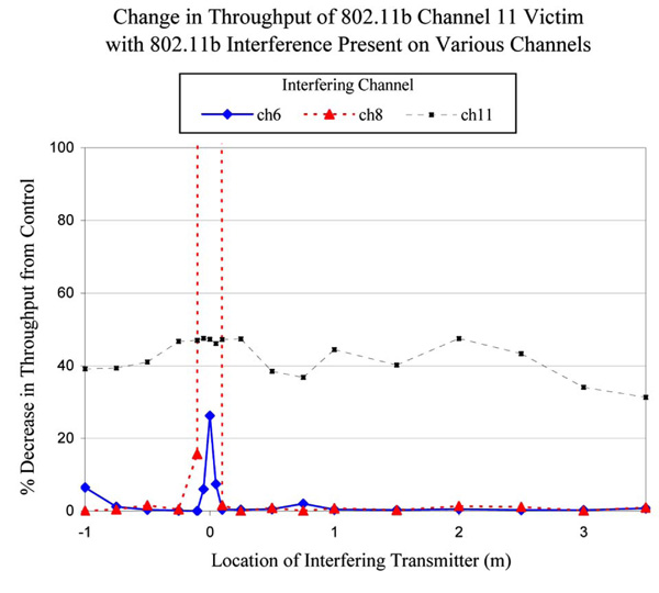
Anechoic chamber results of the percent change in throughput of a victim 802.11b channel 11 communication while an interfering 802.11b communication is present. Vertical lines for the case of interfering channel 8 represent a breakdown of the victim communication at (-.05 m), (0 m), and (.05 m).
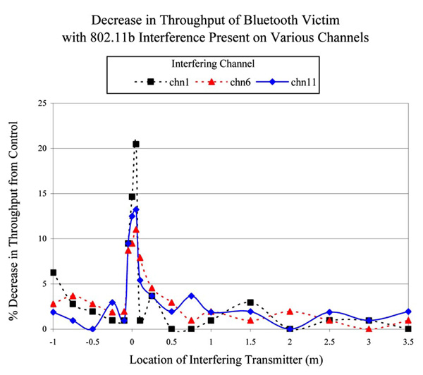
Anechoic chamber results of the percent change in throughput of a victim Bluetooth communication while a interfering 802.11b communication is present.
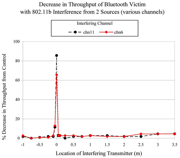
Anechoic chamber results of the percent change in throughput of a victim Bluetooth communication while two interfering 802.11b communications are present. Vertical lines for each case represent a breakdown of the victim communication at (0 m).
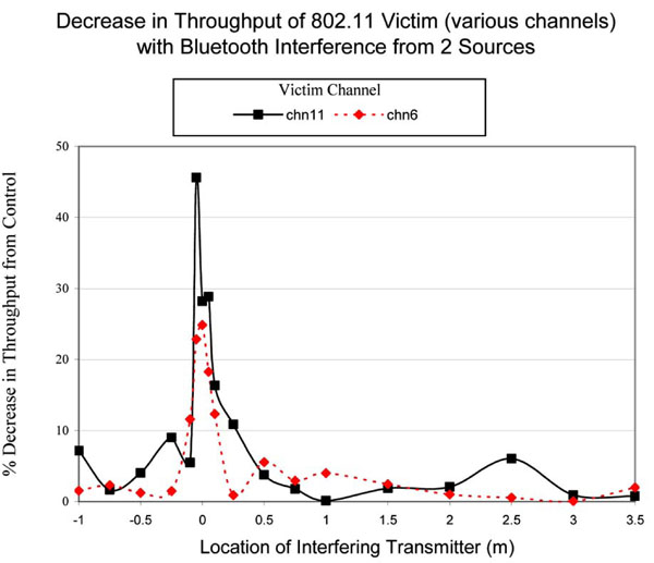
Anechoic chamber results of the percent change in throughput of a victim 802.11b communication while two interfering Bluetooth communications are present.
Anechoic chamber results of the percent change in throughput of a victim 802.11b communication while two interfering 802.11b communications are present.
Test setup inside full anechoic chamber. Emission level read at distances away from transmitting PDA while receiving PDA on opposite side of room.
Tests
Testing was performed by first initializing a communication link between the victim transmitter and the receiver. This link was established and a file transfer was started. Transfer file sizes were 100 MB for 802.11b and 700 kB for Bluetooth. Twenty seconds after the transfer started the interfering field was introduced. The interfering field was on for 90 seconds and then turned off. The victim link was then allowed to finish the file transfer. Average transfer time without interference was 260 seconds for the 802.11b transfer and 360 seconds for the Bluetooth transfer. Throughput was measured by taking the file size and dividing by the time to transfer. Data integrity was verified using a MD5 algorithm. Breakdown was defined when the victim link could not transfer the file and all communication was lost between the receiver and transmitter. Six throughput measurements were performed for each test, three for the control case (without interference) and three for each case with interference. All data reported is an average of the three measured throughputs. Five separate tests were performed for a victim link.
Test 1 - The first test was the radiated immunity test from the FDA recognized EMC standard, IEC 60601-1-2 [11]. This subjects the victim to 1 kHz AM signals between 80 MHz and 3 GHz increasing in 1% frequency increments with a 2 second step dwell. The victim device was exposed to 10 V/m RMS electric field strength. However, the IEC 60601-1-2 standard ignores all in-band testing. This means that frequencies where the device is operating do not need to be tested. This is not adequate for such wireless devices because of the extreme popularity of consumer products using the same technologies that all operate in the same band (creating in-band interference). The aim of this test is to show what EMC testing is typically performed for a medical device.
Test 2 - An ‘Alternative CDRH (Center for Devices and Radiological Health) In-Band Test’ was performed that included testing of all in-band frequencies (22 MHz bandwidth) at 3 V/m for an 802.11b channel. Twenty-three individual frequencies were tested from 2451-2473 MHz. Each frequency was tested for the same total time period as the previous IEC 60601-1-2 test. The aim of this test is to show what tests are being missed in band during 60601-1-2 testing.
Test 3 - Also performed was a ‘CDRH SF Threshold Test’ which tested the victim link for the same amount of time as the IEC EMC 60601-1-2 test and used the same AM scheme, but did not sweep through frequencies. A single frequency, f, was chosen and a threshold was found (in electric field [V/m]) where the wireless technology performed without significant decrease in throughput (10%) or breakdown. This frequency was chosen to be the center frequency for an 802.11b channel when testing an 802.11b victim link. When testing a Bluetooth victim link the frequency was chosen to be in the Bluetooth frequency band. The aim of this test is to show the effect of a generic in-band emitter on a communication link. Similar threshold tests were performed using
Test 4 - Similar threshold test as in Test 3, but with a typical 802.11b signal as an interferer. The 802.11b signal used was an 11 Mbps bit rate with CCK modulation. PLCP (physical layer convergence protocol) header and MAC parameters were chosen in accordance to the 802.11b specification [12].
Test 5 - Similar threshold test as in Test 3, but with a typical Bluetooth signal as an interferer. The typical Bluetooth signal used in test type 5 was of PRBS (pseudo random binary sequence) type PN15 with 2FSK modulation scheme. All parameters were chosen from the Bluetooth specification [13] .
Results
Testing an 802.11b channel 11 communication (Test 1) reported no breakdowns and insignificant decrease in throughput (less than 10%).
Our ‘Alternative CDRH In-Band Test’ (Test 2) results are shown in Fig. (2). Breakdown status occurred at an interferer frequency of 2462 MHz and 2466 MHz. The results show considerable decrease in throughput when the interfering signal’s frequency is close to the victim’s center operating frequency (2462 MHz).
Our ‘CDRH SF Threshold Test’ (Test 3) of an 802.11b channel 11 victim link was tested against a AM signal at the channel 11 center frequency of 2462 MHz. Results showed that even at the lowest measurable test value (0.5 V/m) the 802.11b link reached breakdown status.
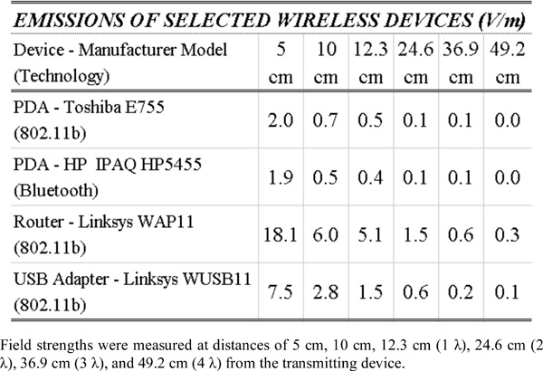
Testing the 802.11b channel 11 victim link against an 802.11b signal (Test 4) at the same center frequency performed better than our ‘CDRH SF Threshold Test’. Although some decrease in throughput was observed at 0.5 V/m, breakdown did not occur until above 5 V/m. As shown in Table 1 the average 802.11b device would need to be closer than 10 cm to emit an electric field strength of 5 V/m. Throughput was recorded from 0.5 V/m up to 5 V/m and is shown in Fig. (3). Testing the 802.11b channel 11 victim link was also performed for 802.11b interfering signals at 2457 and 2437 MHz. These represent the neighboring channel 10 and the first non-overlapping channel 6, respectively. Against channel 10 the victim communication reached breakdown status at 4 V/m. According to our emission measurements the average 802.11b device would need to be closer than 10 cm to emit an electric field strength of 4 V/m or greater. No breakdowns occurred for interfering source channel 6, but for fields of 10 V/m a 30% decrease in throughput was measured.
Emissions (in v/m) from Wireless Devices
 |
A Summary of Worst-Case Findings from Tests Done in the GTEM in Anechoic Chamber
 |
Testing the 802.11b channel 11 link against a Bluetooth interferer (Test 5) at the same center frequency (2462 MHz) revealed similar results to our ‘CDRH SF Threshold Test’. At 0.5 V/m there was a 35% decrease in throughput. Field strengths of 1.0 V/m and higher caused breakdown. Based on our emission measurements, the average Bluetooth device would need to be closer than 10 cm of the 802.11b link to cause breakdown status. This is a worst-case situation because the interfering Bluetooth signal was tested at the 802.11b’s center frequency. In real-life devices the Bluetooth signal would be hopping in a 79 MHz wide band from 2402 MHz to 2480 MHz and would not reside at the 802.11b’s center frequency for more than 625 microseconds.
For a Bluetooth victim, testing in accordance with the IEC 60601-1-2 EMC standard (Test 1) showed no breakdowns and less than a 5% decrease in throughput.
The ‘Alternative CDRH In-Band Test’ (Test 2) was not performed because Bluetooth uses a pseudo-random frequency hopping technique. This test would not be repeatable and would not produce any meaningful results. However, this test was performed for an 802.11b victim because the center frequency and channel bandwidth are known in advance.
Our ‘CDRH SF Threshold Test’ (Test 3) at 2462 MHz revealed a 16% decrease in throughput, but no breakdowns. This includes testing up to 10 V/m. The slight decrease in throughput and lack of breakdowns is not surprising because the Bluetooth signal is hopping and would not dwell at 2462 MHz for any significant amount of time.
Testing the Bluetooth signal against an interfering 802.11b channel 11 signal (Test 4) up to 10 V/m showed no breakdowns and a maximum 36% decrease in throughput.
Testing the Bluetooth victim link against an interfering Bluetooth signal (Test 5) proved to be very stable. No breakdowns or decrease in throughput were observed in the victim link.
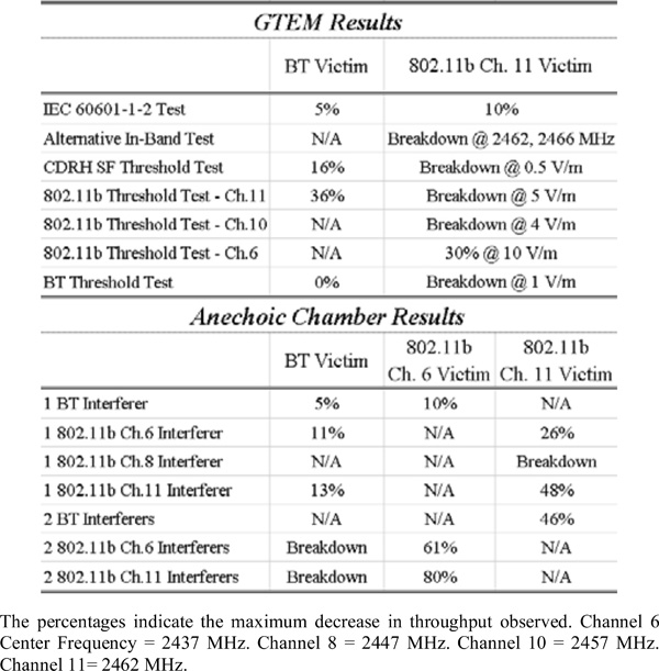
The first half of Table 2 shows a summary of worst-case findings from tests done in the GTEM. It shows how the Bluetooth and 802.11b victims responded to all of the different interfering sources. The percentages indicate the maximum decrease in throughput observed.
ANECHOIC CHAMBER TESTING
Devices
To create 802.11b communications to use as interfering and victim links, we used the following configuration. We installed Linksys 802.11b USB network adapters in four desktop PCs with a Windows 2000 operating system and a Pentium II 350 MHz CPU. Also used in various setups were: a Dell Lattitude D400 notebook with a Windows 2000 operating system and a Pentium M 1.7 GHz CPU; a 1.5 GHz Pentium 4 PC with a Windows 2000 operating system; and a 333 MHz Pentium PC with a Windows XP operating system. A Linksys 802.11b access point, model WAP11, connected by an Ethernet port was used when more than one 802.11b communication was acting as an interferer. Custom 802.11b software was used to monitor the 802.11b file transfer. The software uses WinPcap 3.1b, an open-sourced library for examining packets sent and received from the network card. While running the software, the time of transfer is displayed for each file sent and received. The data integrity was checked at the file level using the MD5 algorithm described earlier. For Bluetooth testing, three P5455 IPAQs and one Compaq IPAQ model 3970 were used to operate and transmit the Bluetooth data. The Bluetooth communication was handled using the same custom software as described previously in the GTEM testing section.
Setup
The testing of the wireless devices was performed in a semi-anechoic chamber of dimensions 6 x 3 x 3 meters. An anechoic chamber is a shielded room with radio frequency-absorbing interior panels. The absorber minimizes reflections of EM waves inside the chamber. The shielding prevents spurious EM interference from entering the chamber. Four tests were used to simulate the possible scenarios with one victim link and one interfering link. Three other tests were used to determine the effects from multiple interferers.
Tests
All tests were performed to analyze throughput, data integrity and breakdowns of a victim link in the vicinity of one or two interfering links. Throughput was measured by taking the file size (which remained constant: 30 MB for 802.11b and 500 KB for Bluetooth) and dividing by the transfer time. Data integrity was verified using a MD5 algorithm. Breakdown was defined when the victim link could not transfer the file and all communication was lost between the receiver and transmitter. The aim of the following tests was to show the effect of in-band interferes on wireless communication. Each test represents a different possible combination of victim and interfering communication link.
Test 1 - In the first test, two 802.11b networks were introduced into the chamber (Fig. 4). Each network was created by connecting one of the Pentium II PCs to another Pentium II PC via a Linksys USB 802.11b network adapter connected to each computer. The computers were linked in adhoc mode. The subjects of the test were always at the same height (1 m) and setup in a linear manner. To aid in describing the setup and locations of each wireless device, a linear coordinate system in meters was used. The exact reference point of the adapters is the base of the antenna. The victim link was an 802.11b system operating on channel 11, with the victim transmitter and the victim receiver one meter apart, (-1 m) and (0 m) respectively. The interfering link was a channel 6 802.11b communication with the interfering transmitter initially located at (-1 m) and interfering receiver located at (4 m). In tests 1-4 the only varying position was the interfering transmitter (ITx). The file transferred on the victim link was a 30MB random text file. During interference, the files were sent twice and an average was taken. This average was then compared to a control case without interference. The interfering signal consisted of the same 30MB file transferred repeatedly throughout the victim’s time of transfer. Victim transfer times were recorded with the interfering transmitter at locations (-1 m), (-0.75 m), (-0.50 m), (-0.25 m), (-0.10 m), (-0.05 m), (0 m), (0.05 m), (0.10 m), (0.25 m), (0.50 m), (0.75 m), (1 m), (1.5 m), (2 m), (2.5 m), (3 m), and (3.5 m). Measurements from more locations were performed when the interfering transmitter was close to the victim receiver, because significant delays were found occurring in this region. This test was then repeated with the interfering channel set to 8, which is centered at 2.447 GHz and overlaps channel 11 by 7 MHz, and channel 11, the victim channel.
Test 2 – The second test involved an 802.11b network as the victim with an interfering link consisting of two HP5455 PDAs communicating via Bluetooth. The 802.11b network was created by connecting one of the Pentium II PCs to another Pentium II PC via two Linksys USB 802.11b network adapters in adhoc mode. The 802.11b victim was tested while on channels 1 and 6. Because the data transfer rate of Bluetooth is much lower than 802.11b, a 500 KB file was sent repeatedly to act as the interfering signal. The victim transmitter and the victim receiver were one meter apart, (-1 m) and (0 m) respectively. The interfering receiver was set at position (4 m) and the interfering transmitter was moved along the same path as in the previous test. Again the 30MB file was sent twice and an average was taken to be compared to the control case with no interference.
Test 3 - The third test involved using the HP5455 PDAs communicating via Bluetooth as the victim link and having one 802.11b network on various channels as an interferer. The 802.11b network consisted of two Pentium II PCs connected in adhoc mode through two Linksys USB network adapters. The victim transmitter and the victim receiver were one meter apart, (-1 m) and (0 m) respectively. The interfering receiver was set at position (4 m) and the interfering transmitter was moved along the same path as in the previous tests. The interfering signal consisted of the 30 MB file transferred repeatedly throughout the victim’s time of transfer. This was handled similar to the previous tests with the victim link transferring the 500 KB file in the presence of continuous 802.11b interference.
Test 4 - The fourth test involved one PDA Bluetooth connection as the victim link and another PDA Bluetooth connection as the interfering link. Two HP5455 PDAs were used as the victim link, where a HP5455 PDA and a Compaq IPAQ 3970 were used as the interfering link. The 500 KB file was sent repeatedly to act as interference and the same 500 KB file was transferred as the victim communication. The victim transmitter and the victim receiver were one meter apart, (-1 m) and (0 m) respectively. The interfering receiver was set at position (4 m) and the interfering transmitter was moved along the same path as in the previous tests.
Test 5 - The fifth test involved testing two HP5455 PDAs communicating via Bluetooth as the victim link and two separate 802.11b communications as the interferers. The 802.11b communications consisted of two Pentium II PCs using the Linksys network adapters sending data to a single PC using the Linksys router. Using the router required the networks to all be on the same channel and to be in infrastructure mode as opposed to the adhoc mode used for the single communications. In infrastructure mode all devices are connected to a centralized access point which serves as the backbone to the wireless network. Because the custom 802.11b software could not support two data links on the same computer, a Microsoft Windows copy command was used. The interfering transmitters (Linksys USB network adapters) were placed side by side at (0 m) and to avoid excess movement of components the victim receiver was moved along the same path as the interfering transmitter in the previous tests. Since the separation of the victim components was changing, control cases without interference were taken for each point. The 500 KB file was then sent with interference present and the data was recorded.
Test 6 - The sixth test involved testing an 802.11b network consisting of two communicating Pentium II PCs using the Linksys USB network adapters in adhoc mode as the victim link and four PDAs communicating via Bluetooth as the interferers. The PDAs formed two different adhoc Bluetooth networks, each with the transmitter at (0 m) and the receiver at (4 m). The victim transmitter was set at position (-1 m) and the victim receiver was moved along the same path as interfering transmitter in Test 1. Both were transmitting the 500 KB file repeatedly. The victim link sent the 30 MB file and the time of transmission was recorded for each position.
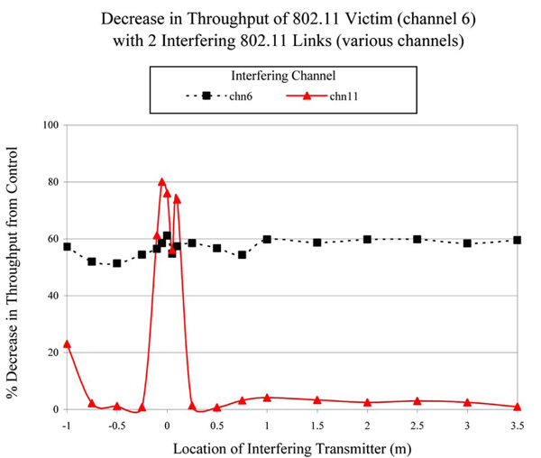
Test 7 - The seventh test involved testing one 802.11b network consisting of two communicating computers using the Linksys USB network adapters as the victim. The victim computers, set to adhoc mode, were the Dell Latitude notebook as the victim transmitter and the Pentium PC as the victim receiver. The notebook used the same WPC55AG 802.11 wireless adapter as used in the GTEM testing whereas the Pentium PC used a Linksys USB network adapter. The interferers were two 802.11b infrastructure networks consisting of two Pentium II PCs using the Linksys USB network adapters, side by side at (0 m), connected to the Pentium IV PC using the Linksys router at (4 m). The victim transmitter was set at position (-1 m) and the victim receiver was moved along the same path as the interfering transmitter in test 1. In this test, the victim channel was set to 6 for all the tests and the interfering channel was switched between 11 (no overlap), 8 (partial overlap), and 6 (full overlap). Results for the transmission of the 30 MB file were recorded at each position of the victim receiver.
RESULTS
Fig. (5) shows testing of the 802.11b channel 11 victim link against an interfering signal of 802.11b on channels 6, 8, and 11 (Test 1). When the interfering signal was on channel 6, the only significant decrease in throughput (26%) came while the interferer was on top of the victim receiver. This is expected since channel 6 does not overlap channel 11. When the interfering signal was changed to channel 8, a communication breakdown occurred when the interfering transmitter was brought within 5 cm of the victim receiver. It was only after the interfering signal was manually stopped that transmission would restart. However, when the interferer was the same channel as the victim, channel 11, the communication was never lost, but had a considerable decrease in throughput (31-48%) regardless of the position of the interferer. The three control cases showed a variation less than 2%.
Next an 802.11b victim on channels 1 and 6 was tested against the interfering PDA Bluetooth connection (Test 2). Both channels behaved similarly, with decreased throughput only when the interferer was within 5 cm of the victim receiver. The maximum decrease in throughput was observed from channel 1 at 21%. A 5% variation in the control cases was measured.
The opposite situation, when the PDA Bluetooth connection was the victim and the 802.11b connection the interferer (Test 3) reported the same general trend. This is shown in Fig. (6). Decreases in throughput, up to 21%, were only seen when the interferer was within 5 cm of the victim. The control cases showed throughput variations of up to 5%.
When testing the Bluetooth connection and having another Bluetooth connection as the interferer (Test 4) throughput decreased by no more than 5%. This decrease however was within the 5% variation seen in the control cases of the Bluetooth communication.
Fig. (7) shows testing of a Bluetooth victim against two separate 802.11b interferers (Test 5). The important parameter in these tests was the relative location between the receiver and transmitter. When the victim receiver was on top of the interfering transmitters, the Bluetooth connection could not be established while the 802.11b communication was possible. The variation of the control case was less than 3%.
Fig. (8) shows the testing of one 802.11b communication in the presence of two Bluetooth communications (Test 6). The interference from the Bluetooth caused a significant decrease in throughput (18-46%) while the victim was within 5 cm of the interfering transmitter. The variation in the control cases here was larger than previous tests at 8%.
Fig. (9) shows the case of one adhoc 802.11b network being interfered with by two computers communicating in 802.11b infrastructure mode (Test 7). The victim channel was always set on channel 6. While the interferer was set on channel 11, large decreases of throughput (50-80%) were seen when the victim receiver was within 10 cm of the interfering transmitters. When the interferer channel was changed to channel 6, the same channel on which the victim was transmitting, the decreases in throughput were between 51 and 61% for each position tested. Finally, testing with the interferer on channel 8 proved again to be the most interesting case. Testing on this channel could not be completed because the interfering communications consistently broke down in the presence of the victim communication. The variation of the control cases on this test was less than 6%.
The second half of Table 2 is a summary of worst-case findings from tests done in the anechoic chamber. It shows how the Bluetooth and 802.11b victims responded to all of the different types and numbers of interfering sources. The percentages indicate the maximum decrease in throughput observed. It was previously noted that not all test combinations would be meaningful. Additionally there are an infinite number of test possibilities. Tests not completed in the table are noted as N/A. The testing reported in this paper required one thousand hours of testing by two individuals.
EMISSION MEASUREMENTS
To help compare the GTEM and anechoic chamber tests, and to have an understanding of field strengths emitted by these devices, several emission measurements were performed. With emission data it is possible to compare the electric field strength thresholds from the GTEM testing with distances (as were recorded in the anechoic chamber testing). To perform the emission measurements, two wireless devices (a transmitter and receiver) were placed inside the anechoic chamber to establish wireless communication. A 2450 MHz open-ended rectangular waveguide (WR430) antenna (with a calibrated gain of 7.5 dB) was used as a receiver which was connected to the Agilent spectrum analyzer model 8465E. Emission data was taken at distances of 5 cm, 10 cm, 12.3 cm (1 λ), 24.6 cm (2 λ), 36.9 cm (3 λ), and 49.2 cm (4 λ) from the transmitting device. The receiving device was located in the other side of the anechoic chamber to increase transmitting output power as shown in Fig. (10). The distance that maximized output power was 4.5 m. The transmitting devices were placed and tested in three different orientations (X, Y, and Z) at four different angles (0°, 90°, 180°, and 270°) to identify the variations in maximum power received by the open-ended waveguide. Channel 6 (2437 MHz) was chosen for the 802.11b link. Table 1 shows the measured maximum electric field in V/m from the devices with respect to each distance.
DISCUSSION
The findings in both the GTEM and anechoic chamber testing show Bluetooth to be a robust wireless communication system. The close agreement of the findings also helps to prove the validity of both testing procedures. While being exposed to 802.11b, the Bluetooth link never reached breakdown in either the GTEM or anechoic chamber tests. In the GTEM, the 802.11b interferer caused 36% delays at 10 V/m to the Bluetooth link. In the anechoic chamber tests 13% delays were seen at a distance of 5 cm away from the Linksys USB 802.11b network adapter. At 5 cm, the Linksys USB 802.11b network adapter recorded an emission of 7.5 V/m. Few effects were shown on the Bluetooth victim during interference by another Bluetooth device or signal.
The results show that our 802.11b devices did not coexist as well as our Bluetooth devices. For non-overlapping channels where little interference is to be expected, a significant decrease in throughput was found in the GTEM and anechoic chamber testing. PDA victims using 802.11b were also affected, both in throughput and breakdown, by low power AM signals in the same frequency range for the GTEM tests. For same channel 802.11b interference the anechoic chamber tests showed significant delays and the GTEM tests revealed communication breakdowns. However against Bluetooth interference, the 802.11b victim operated well, only showing minimal delays in the anechoic chamber testing. A comparison between GTEM and anechoic chamber tests for 802.11b is not reasonable due to testing different victim devices. Each victim has different receiver sensitivity levels that make them behave differently.
Multiple interferer testing was only performed in the anechoic chamber and cannot be compared to any tests in the GTEM. However, there are some valuable findings from this testing. While exposing a Bluetooth victim to one 802.11b interferer 5 cm away, a 13% decrease in throughput was observed. However, exposing the same Bluetooth victim to two 802.11b interferers at the same distance, a communication breakdown was found. Exposing an 802.11b victim to one Bluetooth interferer 5 cm away, a 21% decrease in throughput was observed. Exposing the same 802.11b victim to two Bluetooth interferers at the same distance, the decrease in throughput rose to 46%. Exposing an 802.11b victim to one 802.11b interferer on the same channel, the decrease in throughput averaged 43%. Exposing the same 802.11b victim to two 802.11b interferers on the same channel, the decrease in throughput averaged 57%. While exposing an 802.l1b victim to one 802.11b interferer on a non-overlapping channel, the only significant decrease in throughput was 26% at (0 m). However, exposing the same 802.11b victim to two 802.11b interferers on a non-overlapping channel had severe delays of 61-80% when the interferer was within 10 cm. Adding interference from multiple devices decreases throughputs and in some cases causes communication breakdowns.
Information from the results of these tests can be valuable in determining a technology to be used for a medical device. Some medical device functions may be critical in function but require little throughput. Other functions may want to store large amounts of data for backup or later retrieval and need high throughput, but not require the data be sent in a timely fashion.
CONCLUSION
Taking all testing into account, the Bluetooth PDAs seem to be most reliable. Bluetooth’s limited data transfer rate and range are balanced by its ability to coexist with devices that may be in its environment. Results from both technologies show no breakdowns as long as our devices were greater than 10 cm apart. Depending on throughput criterion, this minimum separation distance may assist in setting up a healthcare network. However, throughput criterion is difficult to guarantee. Our results show that 802.11 throughput varied greatly depending on wireless interferer, number of interferers and separation distance. It is important to realize that different devices implementing the same wireless technologies may behave differently. For this reason simulations and numerical analysis of computer networks need experimental verification. Our testing can be used to validate such simulation tools. Due to the uncertainty of wireless communications it is important that wireless signals such as 802.11b and Bluetooth are tested for coexistence prior to being used in the same vicinity as other high priority wireless communications, especially life-critical medical devices. Wireless coexistence is not automatic, and every possible precaution should be made to ensure the safety and security of patients.