All published articles of this journal are available on ScienceDirect.
Evaluation of the Structural Behaviour of a Unilateral External Fixator for Osteosynthesis
Abstract
Background:
External fixation is an osteosynthesis technique particularly useful in trauma surgery and Damage Control Orthopedics (DCO). However, complications, such as pin loosening and pin tract infections, are fairly common. For reducing thermal damage and infection rates, monocortical pins have been proposed as an alternative to the most used bicortical pins. However, there is a lack of studies regarding their mechanical properties.
Objective:
The aim of the study is to assess the static and dynamic stability of a unilateral external fixator experimentally when applied through monocortical pins for the reduction of femur and tibia fractures.
Methods:
A modular unilateral external fixator was used and a total number of 6 pins were used per test. The static tests were performed in displacement control by applying a vertical displacement to the upper fixture at 1 mm/min until a tension load of 380 N was reached. The dynamic tests were performed by applying a sinusoidal displacement. During each test, forces and crosshead displacements were acquired. Two different stiffness indexes were assessed.
Results:
By comparing the two anatomic regions, it was found that the fixator behaves stiffer when mounted on the femur, regardless of the pins used, while stiffnesses comparable to the femur ones are reached by the tibia when 4 mm diameter pins are used. Static analysis revealed excellent fixator stability when implanted with 4 mm diameter monocortical pins on both anatomic regions. On the contrary, two tibia and one femur samples showed failures at the bone-pin interface when 3 mm diameter pins were used.
Conclusion:
Dynamic analysis showed no substantial difference between the tested configurations and confirmed the fixator's ability to sustain cyclic loading without further damage to the sample.
1. INTRODUCTION
Osteosynthesis is a surgical technique for the treatment of skeletal fractures through the implant of mechanical devices in order to stabilize and fix the injured skeletal segment [1]. This technique is particularly useful in injuries that might not benefit from a conservative approach (simple immobilization or casting). Fractures that cannot be properly stabilized by a cast, such as displaced juxta-articular fractures, multiple injuries, or fractures associated with soft tissue damage, are the main indications for fracture fixation and osteosynthesis [2].
Fracture fixation can be classified into internal and external. The technique chosen depends on the type of fracture, soft tissue involvement, and the presence of associated injuries. In particular, external fixation is considered the gold standard technique in Damage Control Orthopaedics (DCO) [3]. DCO is a rapid intervention approach adopted by orthopaedic traumatologist surgeons, which includes the temporary stabilization of the injured skeletal segment using external devices in order to immobilize the fracture site reducing both bleeding and pain, allowing safe mobilization, soft tissues recovery, and wounds care [4].
The main requirements of an optimal external fixation system include (1) ease of use and versatility in order to respond to different indications, (2) ability to restore the anatomical morphology of the bone by aligning the fracture fragments using different spatial configurations, (3) elastic deformability of the system in order to induce micro-movements and (4) stability against external solicitations.
The knowledge of the mechanical characteristics of bone tissue, with particular focus on its behaviour under load, is without doubt fundamental for deeply understanding various physiological and pathological conditions, looking for substitution materials, and investigating possibilities of coupling with other materials and devices.
With a particular regard to external fixation, accurate biomechanical testing is a crucial component of orthopaedic construct innovation. Valid biomechanical testing can aid in the selection of fixator configurations, materials, and implantation techniques that result in optimal mechanical stability necessary to facilitate healing [5]. Because of its correlation with the amount of motion at the fracture site, one of the most challenging aspects in testing an external fixator is stiffness, as it may directly affect the time and quality of healing [6-9].
One of the most important aspects of external fixation is the screw-bone interface which represents the point of maximum mechanical strain [10]. As a result, the most common and dreaded complications are pin loosening and infection of the pin tract, which are thought to be related to necrosis of the bone and the surrounding tissue [11]. For reducing bone thermal damage during pre-drilling or pin insertion, monocortical pins have been proposed as an alternative to the most popular bicortical fixation, especially for external fixation during DCO or preceding intramedullary nailing [12]. Nevertheless, to our knowledge, mechanical properties of external fixators with monocortical pins, such as static and dynamic stability, have been poorly investigated.
The present study aims to assess the static and dynamic stability of a unilateral external fixator experimentally when applied through monocortical pins for the reduction of femur and tibia fractures.
2. MATERIALS AND METHODS
2.1. Unilateral External Fixator
A modular unilateral external fixator (Fixus 66, distributed by Unimedical Bio. Tech. Srl, Torino, Italy) was selected for this study. It is composed of a radiolucent carbon bar with an elliptical section (12.3 x 11.1 mm) and a length of 400 mm, four 4-hole aluminium clamps (two at each end of the fracture) for 3 to 6 mm diameter pins, two bar-clamp aluminium adapters that can slide on the bar up to the insertion height of the pins, where the adapter is locked. In this study, a total number of 6 pins were used per test, three for each end with the symmetrical arrangement, two on the right clamp and one on the left clamp. With the aim of testing the relation between fixator stability and pins diameter, self-tapping and self-drilling pins (150 mm long) with 3 mm and 4 mm diameter, respectively, were selected.
2.2. Samples Preparation
In order to neglect the high intrasubject variability linked to the use of cadaveric bones, the external fixator was implanted on 8 simulacra of tibia and 8 simulacra of femur produced by Sawbones (Sawbones, Pacific Research Laboratories, Inc., Vashon, WA). The tibia of 4th generation medium size version (model SKU:3401) was selected and for mimicking the femur diaphysis, a short hollow fiber reinforced epoxy cylinder with 30 mm of outer diameter and 4.3 mm of wall thickness (model SKU:3403-15) was selected. The 16 bone samples were divided into the subgroups according to (1) anatomic region (tibia or femur), (2) bone status (intact or fractured), and (3) pins diameter (3 mm or 4 mm), obtaining 8 subgroups, as summarized in Table 1.
| Anatomic Region | Tibia | Femur | ||
Pins Diameter
 Bone Status Bone Status
|
3 mm | 4 mm | 3 mm | 4 mm |
| Intact | 1 | 1 | 1 | 1 |
| Fractured | 3 | 3 | 3 | 3 |
In the fractured samples, prior to implant, a diaphyseal transverse fracture was created using a surgical saw. The external fixation was thus performed on each sample, following the manufacturer's instructions.
2.3. Testing Set-up
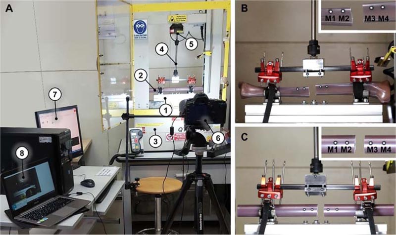
To test the stability of the system in a load configuration that mimics the realistic stress as much as possible to which the bone-fixator construct is subjected in a hospital setting, a fixture for a uniaxial testing machine has been designed to replicate the lifting of the limb by gripping on the external fixator bar. This loading application is compatible both with the manoeuvring performed by the surgeon to check the post-implant stability and with the handling manoeuvring carried out by the medical staff during patient’s hospitalization. The designed testing setup is shown in Fig. (1A).
A lower fixture (Fig. 1A-(1)) able to fix the bone (Fig. 1A-(2)) to the base of the MTS Q-Test 10 Elite (MTS Systems Corporation, Eden Prairie, Minnesota, USA) (Fig. 1A-(3)) was therefore designed, while the upper fixture (Fig. 1A-(4)), equipped with two spherical joints, constrains the vertical movement of the fixator bar to the moving crosshead, adapting to the different positions of the fixator with respect to the bone and avoiding over-constraints. A 2.5 kN load cell (Fig. 1A-(5)) was interposed between the upper fixture and the moving crosshead. Each test was recorded with a full-frame digital camera (Canon EOS 5D Mark II) equipped with an autofocus lens for macro photography (Canon EF 100 mm f /2.8 Macro USM) and positioned on a tripod (Fig. 1A-(6)). Tests and videos were acquired simultaneously from two computers (Fig. 1A-(7) and (8)). Local movements around the fracture zone were measured through the optical tracking of four markers (M1, M2, M3, and M4, Fig. 1B and 1C).
2.4. Mechanical Tests
Two types of mechanical characterization have been designed for the evaluation of two important aspects of external fixation: (1) the static characterization, suitable for evaluating the stiffness of the bone-fixator construct with and without the fracture, and (2) the dynamic characterization, designed to evaluate the stability of the construct when repeatedly stressed. The testing of the external fixator implanted on non-fractured bones, albeit devoid of clinical motivation, is aimed at characterizing the stability of the external fixator in the absence of bone instabilities and producing reference values for comparisons. For this reason, only one test per combination of parameters was performed in the intact configuration.
2.4.1. Static Characterization
Static tests were performed in displacement control by applying a vertical displacement to the upper fixture at 1 mm/min until a tension load of 380 N was reached. The load limit was selected based on the research of Plagenhoef et al. on body segment weight as a percentage of the Total Body Weight (TBW) [13]. The leg mass was, indeed, about 18% of the TBW; considering a TBW equal to 150 kg and a safety factor of 1.4, a load of about 380 N was estimated. During each test, both the mechanical data (i.e., forces and crosshead displacements) and the video data were acquired for further post-processing.
2.4.2. Dynamic Characterization
Following the static characterization, the samples were tested in dynamic conditions applying a sinusoidal displacement. Indeed, given the complexity of calibrating a feedback loop for load controls on such a complex sample, it was preferred to select the sample-specific maximum displacement to be applied in order to reach a tension force of 350 N from the static results. After a 20 N preload, cycles with an amplitude of 1 mm were applied, making sure to reach the maximum displacement previously deduced. For each sample, three dynamic tests, composed of 10 cycles each, were performed at three different rates: 1 mm/min, 5 mm/min and 10 mm/min. It should be noted that the purpose of this characterization is not to study the fatigue behaviour of the external fixator but to evaluate the effect of the repeated stresses. During each test, forces and crosshead displacements were acquired, and the integrity of the samples was assessed at the end of the tests by visual inspection.
2.5. Data Elaboration
Force-displacement plots were produced from static results, resulting in the setting of the zero displacements when a 5 N force was recorded. Obtained trends were revealed to be bilinear in each test. For this reason, a unique stiffness parameter (i.e., the slope of the whole experimental curve) was not computable. Therefore, two different stiffness indexes were assessed, describing the sample behaviour at the beginning and at the end of the load application. In detail, the initial stiffness Ki was computed as the linear regression of the curve in the 5 – 30 N load range, whereas the final stiffness Kf was computed as the linear regression of the curve in the 250 – 350 N load range.
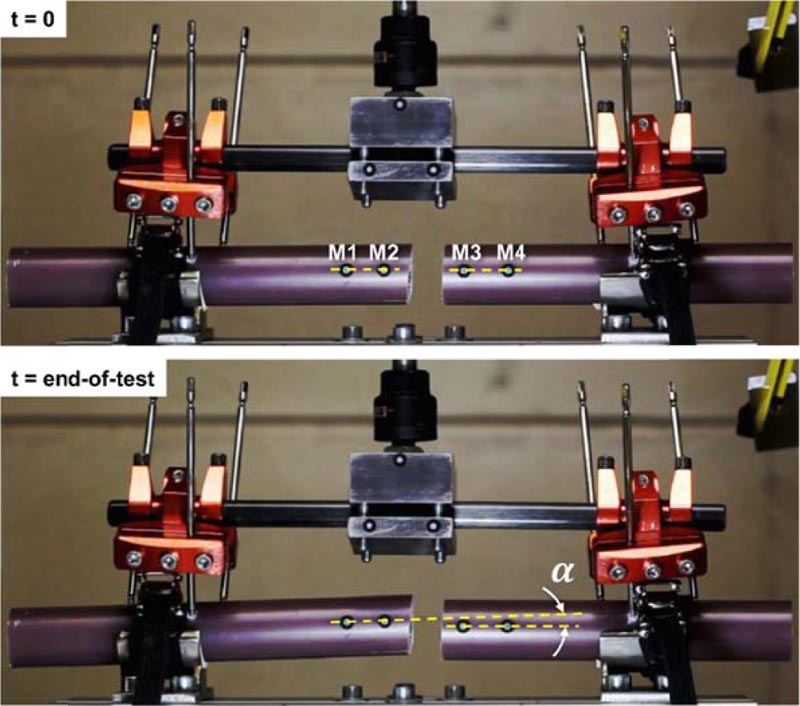
The videos acquired during static tests were imported in the GOM Software 2019 (GOM GmbH, Braunschweig, Germany) to track the displacement of the markers. Two lines were created between markers M1 and M2 and markers M3 and M4, respectively (Fig. 2) and, as a stability indicator, the angle α formed between the two lines was measured along with the test, with respect to the initial reference angle measured at time t = 0.
Dynamic results were post processed through a force normalization with respect to the first force peak of each test. This was considered indispensable since the maximum force values, although calibrated by static tests to be equal to 350 N, turned out to be variable according to the test rate. From the so obtained force-displacement hysteresis loops, areas were computed and compared, being indicative of the energy involved. Energy trends with respect to the cycle number (from 1 to 10) were then fitted with a two-parameter power function in the form y = b xm, aiming to assess the rates of decay m.
3. RESULTS
3.1. Static Characterization
Fig. (3) shows force-displacement trends for the 16 performed tests. The bilinear behaviour is clearly visible in almost every curve, with particular preponderance in the more rigid configurations. Moreover, sudden failures are visible in the configurations with fractured segments and thinner pins, represented by solid red lines. These are due to the failures in correspondence with the pin threads, which generate an instantaneous relative sliding between the pin and the bone.
Focusing on the computed stiffnesses Ki and Kf (Table 2), the initial stiffness was revealed to be systematically higher than the final stiffness, up to 4-fold higher in the intact configurations and up to 3-fold higher in the fractured ones. The only exception is the configurations with tibia and 3 mm diameter pins, which are globally less stiffer and are characterized by a less pronounced bilinearity. By comparing the two anatomic regions, the fixator behaves stiffer when mounted on the femur, regardless of the pins used, while stiffnesses comparable to the femur ones are reached by the tibia when 4 mm diameter pins are used.
The optical analysis allowed the evaluation of the bone segment's stability by maintaining alignment of the segments during load application. Figs. (4 and 5) show that the angle increased for each fractured configuration (intact configurations would generate a null angle increase, therefore, it was not monitored).
| - | - | - | Ki [N/mm] | Kf [N/mm] | ||||
| Pin Diameter | Bone Status | Test # | Tibia | Femur | Tibia | Femur | ||
| 3 mm | Intact | - | 114.1 | 332.3 | 118.7 | 150.1 | ||
| Fractured | Test 1 | 152.0 | 403.4 | 74.8 | 139.7 | |||
| Test 2 | 89.8 | 365.0 | 94.2 | 129.9 | ||||
| Test 3 | 39.8 | 279.2 | 102.1 | 129.4 | ||||
| 4 mm | Intact | - | 574.9 | 426.8 | 139.0 | 149.7 | ||
| Fractured | Test 1 | 247.8 | 304.3 | 112.2 | 115.1 | |||
| Test 2 | 269.9 | 292.1 | 107.3 | 115.7 | ||||
| Test 3 | 364.7 | 372.5 | 130.4 | 140.2 | ||||
Steep angle increases are visible in three 3 mm diameter pin tests, which are the ones characterized by failures in pin holds. On the contrary, 4 mm diameter pins allowed the maintenance of the segment misalignment to be always below 1.7°.
Fig. (6) summarizes the total angle variation experienced by the two anatomic regions, confirming the higher stabilizing effect of the 4 mm diameter monocortical pins.
3.2. Dynamic Characterization
Fig. (7) shows the normalized energy loss trend at three different test rates for a representative sample. The curves revealed to be always almost identical, albeit translated vertically, therefore, the variation in the rate of application of the load led to very similar results in the power fitting procedure. Hence rates of decay m were reported only for the 1 mm/min test rate.
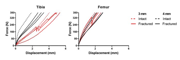
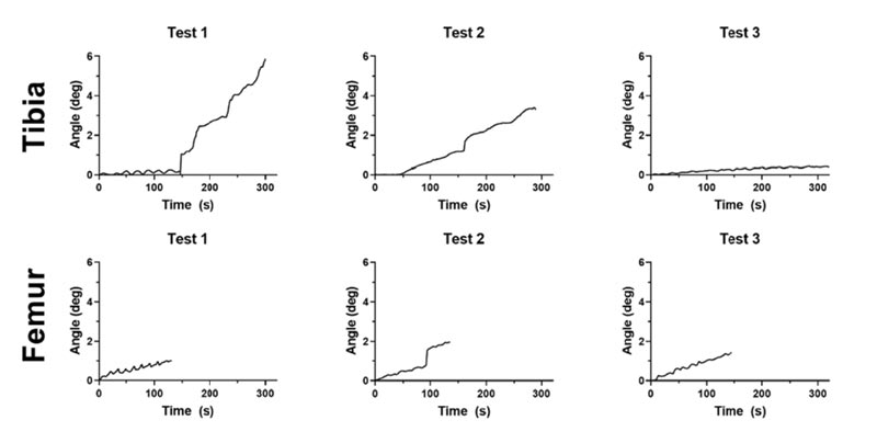
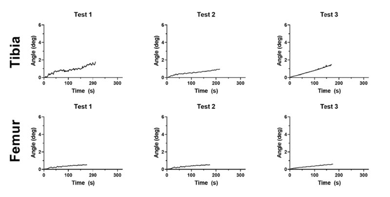
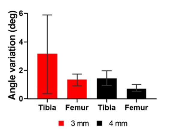
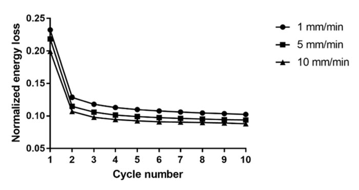
Table 3 lists the rates of decay computed for the 16 tested samples, and no macroscopic differences result from the comparison between both anatomic regions and pin diameters. Indeed, the rate of decay m settles around -2 for each test. Therefore, no substantial differences between configurations arise when the fixator is repeatedly stressed.
| - | - | - | Rate of Decay m | |||
| Pin Diameter | Bone Status | Test # | Tibia | Femur | ||
| 3 mm | Intact | - | -1.80 | -2.50 | ||
| Fractured | Test 1 | -2.06 | -1.83 | |||
| Test 2 | -2.05 | -1.97 | ||||
| Test 3 | -2.11 | -2.26 | ||||
| 4 mm | Intact | - | -2.18 | -1.91 | ||
| Fractured | Test 1 | -2.02 | -2.42 | |||
| Test 2 | -2.19 | -2.12 | ||||
| Test 3 | -2.12 | -2.31 | ||||
From a visual inspection, no further pin-bone damage was noted after the dynamic characterization. The failures indeed occurred exclusively during static stresses, and the application of the dynamic load did not lead to further damage to the samples.
4. DISCUSSION
Although the indications and protocols for external fixation are constantly evolving, it is evident that its peculiar use in DCO has critically improved the survival rate in patients with multiple injuries [14, 15]. Taegar et al. by comparing two groups of patients who underwent DCO procedure, or Early Total Care (h-ETC), concluded that the latter has a higher association with post-traumatic systemic complications [14]. Moreover, the use of external fixation, either as a tool of temporary stabilization before intramedullary nailing [4] or as definitive treatment [16], significantly reduces the blood loss and the incidence of pulmonary complications [15].
However, the medical community remains worried about the potential complications of external fixation [17, 18]. Thermal damage seems to be one of the most significant factors influencing necrosis around the pin tract, resulting in pin loosening and infection [11]. Especially for self-drilling pins inserted at high rotational speeds, the temperatures occurring on the bone surface can reach levels damaging biological tissue [12]. In particular, temperatures around 80 °C were measured during the insertion of 5 mm diameter pins without pre-drilling [12, 19].
The rationale to use monocortical pins includes drilling only one cortex that reduces the total heat production and prevents penetration in the medullary canal in order to diminish the risk of intramedullary infection.
The external fixator stiffness is a crucial factor in ensuring the maintenance of the physiological bone alignment in loaded conditions, therefore, the purpose of the study was to assess static and dynamic stability of a unilateral external fixator applied through monocortical pins. It is reported that the stability of the unilateral frames can be improved by using a greater number of larger-diameter half pins, by decreasing the bone-to-frame distance, and by placing pins out-of-plane to one another [20]. Currently, unilateral fixators entail the insertion of bicortical pins, resulting in the invasion of the medullary canal. However, the insertion of the same pins in a monocortical configuration would guarantee advantages both from a clinical point of view, such as negligible blood loss and prevention of the contamination of the medullary canal and in health management and in the eventuality of having to intervene with the insertion of a stem or an intramedullary nail. The implantation of pins with reduced diameter could be indeed performed under local anesthesia and without employing specialized clinicians, thus allowing a faster patient recovery and a subsequent quick conversion of the temporary fixator.
The structural analysis of skeletal body elements and the biomechanical systems consisting of a bone element coupled with a prosthesis, an implant, or a fracture synthesis device can be performed both numerically and experimentally. There are many examples of clinical problems that have passed from a qualitative assessment to a quantitative evaluation due to their modeling [21, 22] or due to the application of classical experimental methods of structural analysis, both whole-field [23] and punctual techniques [24].
During our analysis, we encountered some limitations; a limited number of pins was used, and a limited number of tests were performed. Moreover, our study was conducted to assess the effect of repeated stresses only and not the fatigue behaviour of the external fixator.
CONCLUSION
In the present study, static and dynamic stability of a unilateral external fixator implanted through monocortical pins were evaluated, focusing on two anatomic regions (Tibia and Femur) and two pin diameters (3 mm and 4 mm). Static analysis revealed excellent fixator stability when implanted with 4 mm diameter monocortical pins on both anatomic regions, reaching high initial and final stiffnesses and low angle variations (< 1.7°) between the bone segments. On the contrary, two tibia and one femur samples showed failures at the bone-pin interface when 3 mm diameter pins were used, with a consequent increase in the higher angle.
The dynamic analysis showed no substantial difference between the tested configurations and confirmed the fixator ability for sustaining cyclic loading without further damage to the sample.
ETHICS APPROVAL AND CONSENT TO PARTICIPATE
Not applicable.
HUMAN AND ANIMAL RIGHTS
Not applicable.
CONSENT FOR PUBLICATION
Not applicable.
AVAILABILITY OF DATA AND MATERIALS
All the experimental data obtained from the static and dynamic tests are available on request (cristina.bignardi @polito.it).
FUNDING
The research was funded by Unimedical Bio. Tech. Srl, Torino, Italy.
CONFLICTS OF INTEREST
This work is the result of a collaboration between the Orthopedics and Traumatology Complex Structure Asl VC of Sant’Andrea Hospital in Vercelli (Italy) and the Department of Mechanical and Aerospace Engineering Politecnico di Torino in Torino (Italy).
Each author certifies that he or she has no commercial associations (e.g., consultancies, stock ownership, equity interest, patent/licensing arrangements, etc.) that might pose a conflict of interest in connection with the submitted article.
Dr. Cristina Bignardi is the Editorial Board Member of The Open Biomedical Engineering Journal.
ACKNOWLEDGEMENTS
Declared none.

