All published articles of this journal are available on ScienceDirect.

A Technique for Mimicking Soft Tissue Manipulation from Experimental Data to a Wave Equation Model for a New Laparoscopic Virtual Reality Training System
Abstract
Background:
The difficulty of laparoscopic procedures and the specific psychomotor skills required support the need for a training system for intensive and repetitive practice to acquire the specific skills. The present VR training systems have some limitations with respect to the soft tissue models in the training system. This is associated with the need for a real-time simulation, which requires a balance between computational cost and accuracy.
Objective:
The primary objective of the study is to develop a two dimensional wave equation model that closely mimics the soft tissue manipulation in a laparoscopic procedure for a VR training system.
Methods:
A novel mathematical model based on the wave equation is prepared to represent the interaction between the laparoscopic tool and the soft tissue. The parameters within the model are determined through experimental analysis of a soft tissue phantom. The experimental setup involves a linear actuator applying force to the soft tissue phantom to generate deformation. Data acquisition is conducted through a camera and a robotic force acquisition system which measures force, displacement of the linear actuator and records a video. Through image processing, the displacements of the markers on the phantom’s x-y plane during its deformation are determined and these parameters are used to develop the model, which finally is validated through a comparative analysis.
Results:
The results from the developed model are observed and compared statistically as well as graphically with the finite element model based on deformation data. The results show that the deformation data between the developed model and the available model is significantly similar.
Conclusion:
This study demonstrates the adaptability of the wave equation to meet the needs of the specific surgical procedure through modification of the model based on the experimental data. Moreover, the comparative analysis further corroborates the relevance and validity of the model for the surgical training system.
1. INTRODUCTION
Laparoscopic surgeries have various environmental constraints for the surgeons, despite the benefits of this procedure for the patients. Both the constraints and benefits are attributed to the smaller incisions used in the procedure. Therefore, surgeons are required to adapt to distinct psychomotor skills, which are specific to laparoscopic surgeries and their constrained environments [1-3]. Teaching hospitals and medical schools have incorporated various training systems to the surgical programs to meet this need. The most commonly used training systems are cadavers on patients and animals. However, these systems are associated with a number of ethical and legal issues due to the risks associated with novice surgeons practicing laparoscopic procedures [4-6]. Virtual Reality training systems are accepted by many medical schools due to the promise of intensive training with the objective assessment of the user’s performance with limited need for expert surgeon supervision [7-11].
1.1. Mechanics of Soft Tissue
VR training systems demonstrate a lot of promise in medical training but also have room for improvement in order to increase the likelihood of skill transference from the training system to an operation room (OR) [9, 10, 12]. The mechanics of soft tissue play an important role in the development of soft tissue models in VR for accurate representations of the interactions and manipulations of the soft tissue with the environment and the tools [1]. There are two components of the soft tissue models that are affected by the mechanical properties of the soft tissue, which are the visual and haptic responses of the material [1, 13]. Therefore, accurate representation of the mechanical and material properties of soft tissue in a training system allows appropriate transference of the acquired skills into an OR environment [10, 14, 15].
Previous studies discuss the importance and effects of force feedback in a surgical simulator [1, 13, 15-17], while this study looks at the visualization of soft tissue deformations and manipulations based on their mechanical properties. Mechanical studies of human skin describe it as a viscoelastic, non-homogeneous and anisotropic material [18]. In this study, the development of a soft tissue model of skin deformations focuses on the dermis because of its major role in the mechanical properties of the skin [19]. The discussed method aims to develop a heterogeneous representation of the skin with separate models for the epidermis, dermis, and subcutaneous fat [18].
1.2. Soft Tissue Models in VR
Presently, there are three main types of soft tissue models used in VR training systems: mass-spring model, finite element model (FEA), and mesh-free model [1, 20]. The Mass-spring model is the most commonly used representation for real-time applications. Despite low accuracy, this model is preferable due to its considerably low computational cost. This model is controlled by the viscoelastic properties of the soft tissue and is based upon the Kelvin-Voight model [20]; therefore, it is made up of nodes, representing the mass, and links, representing the spring [1]. On the other hand, the FEA models are very accurate but are limited by their computational cost. In this model, a mesh of soft tissue is deformed using differential equations of motion, which calculate the vector fields [1, 20]. Accuracy and computational cost, constrain the soft tissue models in VR because they are directly proportional [1, 12]. These factors contribute to the mass-spring model to be the most prevalent method in these applications
VR training systems require real-time manipulations, therefore not only is accuracy important but also the computational cost, which makes the mass-spring model more preferable [1, 12]. However, this model does not account for the heterogeneity of the soft tissue at hand [9, 21]. Therefore, due to the scenario that available models are either inadaptable, inaccurate or incur a higher computational cost, this study is motivated to develop a model that closely mimics the soft tissue, can be adapted for various tissue types and is feasible for real-time application due to the lower computational cost. The application of the model is significant, especially in a training system for laparoscopic surgery, where surgeons have limited information about the operating area and the realism would further enable the user to apply the skills acquired in VR training system in the operating room [9, 10, 12].
2. MATERIALS AND METHODS
2.1. Two-Dimensional Wave Equation to Mimic Skin in VR
In an earlier study [22], the authors present a novel mathematical model, using wave equation, to model soft tissues and their interaction with laparoscopic tools in a VR training system. Engineers to study a structure’s integrity during interaction with vibrations for example, the effects of an earthquake on a building, commonly use wave equations. Therefore, mechanical and civil engineers [23, 24] most commonly use them.
 |
(1) |
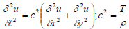
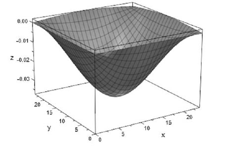
In the preliminary study, a two-dimensional wave equation is used to model thin and elastic membranes (demonstrated in equation 1); therefore, the authors use this mathematical model to represent the distinctive tissues that make up the skin to develop a heterogeneous material. In equation 1, T is the initial tension in the membrane (Newton), ρ is the density of the membrane (kg/m3), the differential function u(x, y, t) represents the solution’s changes with respect to the inputs: x, y coordinate (meter), and time variable t (second) [25] and c is the real non-negative coefficient (m-2s-2).
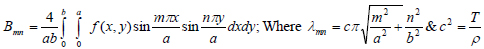
This model utilizes equations (2) and (3), through which solution for the two-dimensional wave equation is found using initial and boundary conditions. In the solution, is the Euler formula whereas represents the effect of the initial velocity [25], and f(x, y) gives the initial displacement while, m and n are positive integers which are assumed to be one in this model. Also, a, b represents the dimensional boundary condition that has been used within the analysis. The variables and functions defined as the initial and the boundary conditions are determined experimentally through a maximum radius of marker, as illustrated in subsection 3.3. Finally, λmn is the eigenvalue of the vibrating membrane such that the frequency of umn is λmn /2π.
 |
(2) |
 |
(3) |
This mathematical model incorporates literature values for the mechanical and material properties of the soft tissue to create a simulation of soft tissue and tool interaction. A mathematical model is developed for each of the three layers of the skin: epidermis, dermis, and subcutaneous [22].
2.1.1. Preliminary Validation Study
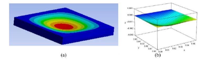
For the preliminary validation study, the authors develop a heterogeneous material for a finite element analysis (FEA); one of the most accurate computer based models [1, 14]. A static structural study, with increasing force, is performed on the material to collect the maximum deformation over a time period [22]. The novelty of the preliminary validation study is established by the fact that the assessments of previous VR training systems’ visualization are based on qualitative information from user responses to questionnaires [26-28]. The results, from the wave equation model and FEA model, suggest the means of data from the two models are equal, which would be expected as they model the same material, the skin. Despite the similarities between the two models, the wave equation model shows a shorter computation period, therefore suggesting the same level of accuracy as a finite element model with less computational cost. Fig. (1) demonstrates a comparison between the two computer based models of the dermis; a layer of the skin [22].
2.1.2. Limitations of the Validation Study
Despite results showing high variability in the validation study [22], the authors address various limitations in the validation study. One such limitation is the comparison of the wave equation model with another computer-based model, both of which are highly idealized. Along with that, the literature values of the soft tissue are used to represent their behavior and may not account for essential deformation related data. Therefore, there is a need for a study, which observes the mechanical behavior of soft tissue during a manipulation to closely mimic what the surgeon would observe in an OR. This is important because of the significance of visual cues in laparoscopic surgery [5, 15].
These limitations address the need for a study that looks at the behavior of soft tissue in a physical setup to further improve the present models. Therefore, this paper presents an experimental setup to collect data during a soft tissue phantom manipulation and applying it to a two-dimensional wave equation model. The results are presented and discussed to support the use of this study and model as future techniques to customize soft tissue in VR training systems and validating the use of wave equation to model tissue interaction with laparoscopic tools. Lastly, demonstrating how the proposed model can be applied to the VR to provide an accurate model with a low computational cost.
2.2. Research Overview
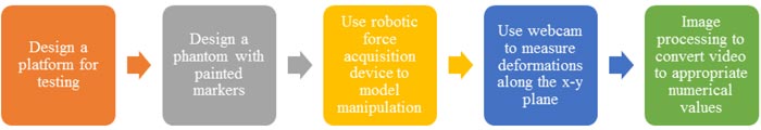
Fig. (2) shows an outline of the steps taken to achieve the aim of this study; to collect data from a soft tissue phantom and develop a wave equation model to implement in a VR training system. The design of this system is inspired by previous studies that look at the effects of needle insertion into a phantom to observe and model the behavior of the soft tissue during an interaction with a tool in a virtual environment [29, 30]. Ten trials are performed for this experiment to check for repeatability and remove the likelihood of random error and these experimental data are illustrated in Subsection 3.2.5.
The complete system for the experiment is displayed in Fig. (3) with labels for major components, which are discussed in further detail in the following subsections. This includes the design of a platform required for the placement of the soft tissue phantom during testing. In this study, the soft tissue phantom is soft silicone, which is deformable, much like human skin, which is the focus of this study. Black markers are painted onto the phantom to observe the movement in the phantom during repeatable manipulation. A robotic force acquisition device is placed above the platform to mimic soft tissue manipulation. Data is collected from a webcam; therefore, image processing is an essential step towards gathering relevant data.
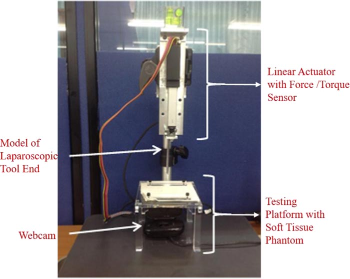
2.2.1. Testing Platform and Soft Tissue Phantom
The testing platform is a plate of acrylic glass with a 3 cm radius hole at the center. This hole is to give way to the deforming soft tissue phantom when manipulated by the robotic force acquisition device. This plate sits on four legs at each edge; the dimensions of the legs are: . The height of the testing platform is 7 cm to allow the laparoscopic tool end, attached to the robotic force acquisition device, to move downwards without hitting the bottom surface of the testing system. This platform also includes two rectangular holders to hold the phantom in place and prevent any tear during the manipulation of the phantom.
The soft tissue phantom is a soft silicone: XIAMETER RTV-3498 NT by Dow Corning (Michigan, USA). For every 100 grams of RTV-3498 NT, 30 grams of DC 200 oil and 5 grams of 81F NW curing agent are added to the mixture. The phantom is white therefore, for the most contrast, the markers are painted in black onto the phantom.
2.2.2. Robotic Force Acquisition Device
The robotic force acquisition device consists of three main components: the linear actuator, the force/torque sensor [17], and a simple model of a laparoscopic tool, shown in Fig. (4). The linear actuator that moves the end effector is Firgelli’s L16 (WA, USA). On the other hand, the force/torque sensor is ATI’s Nano17 (NC, USA).
The needle in the original system [17] is replaced with a model of a laparoscopic tool, as shown in Fig. (4). This attachment is 7 cm long and 1 cm wide.
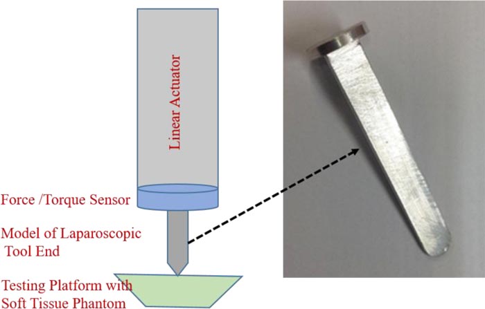
The coordinate system of the plane is defined to match, the one used in the wave equation model in the preliminary studies. Therefore, the plane along the phantom is the x-y plane (x-axis spans left to right and y-axis spans from inside to outside), whereas the direction of deformation (up and down) is u (x, y, t) or the z-axis.
This device is used to create a simple manipulation of the soft tissue, similar to the wave equation model in the preliminary studies by the authors [22]. Therefore, the robotic force acquisition device is used to push down on the soft tissue, after which it returns to the original position where the phantom is not deformed or interacting with the tool.
2.2.3. Webcam
Along with force and z displacement, from the respective sensors, another set of data collected in this study is the video collected using a webcam. The webcam, Logitech HD Webcam C525 (CA, USA), is connected to MATLAB R2017a using a model in Simulink, which operates through blocks from the Image Acquisition Toolbox and the Computer Vision System Toolbox. The camera is placed under the testing platform, where the lens is facing the bottom of the phantom, which is painted with markers in a grid. The analysis of the data collected from the webcam is discussed in further detail in the next section, Image Processing.
Since the data is collected as images, the displacements are measured in pixels; therefore, the authors have implemented a conversion factor to go from pixels to mm. This is achieved by taking an image of a ruler on the platform and determining the number of pixels that make up a cm and finding the respective relationship between the number of pixels and mm.
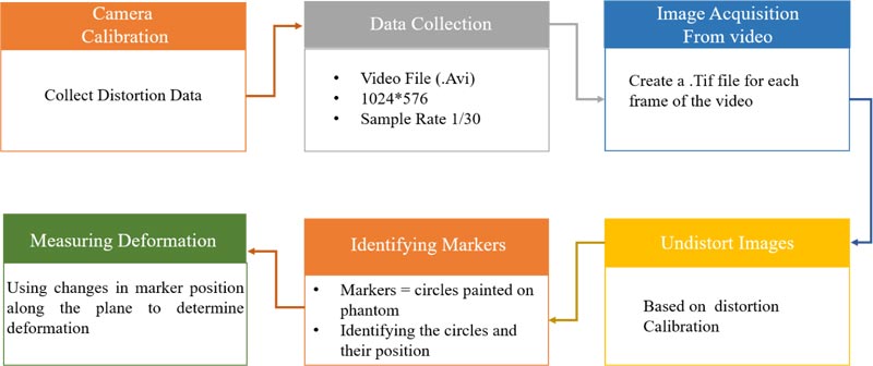
2.3. Image Processing
The image processing is performed in MATLAB R2017a and involves converting the collected video into images, which are modified and analyzed to measure the changes in the x-y plane of the soft tissue. The steps of image processing utilized in this study are listed in Fig. (5) and will be discussed in further detail in this section. This section comprehensively depends on functions provided by MATLAB R2017a.
3. EXPERIMENT AND RESULTS
3.1. Experimental Setup
This study shows the potential of the experimental setup to be used to study any soft tissue of interest, and therefore allow the program to develop a wave equation based on the needs of the procedure or using patient specific data. This study uses silicone, but similar steps can be followed to measure the behavior of a soft tissue. A limitation of this study is the fact that only the simple manipulation of the soft tissue, where it is pushed down and returned to its original shape with a linear motion. Therefore the non-linear motion of the tool and its effect on the soft tissue’s deformation would help improve the wave equation model developed in this study.
3.2. Image Processing
Image processing, in this study, is very important as it is used to observe the deformation of the soft tissue phantom in the experiment and also the selection of imaging methods. The calibration toolbox [31], is used to undistort the images from the video, which therefore results in small changes to the original images. This change allows for the removal of some device associated error from the webcam that is used in this experiment.
3.2.1. Camera Calibration
The authors start with camera calibration for the specific webcam in this experiment. This involves using the camera calibration toolbox designed by Jean-Yves Bouguet [31]. This toolbox requires the user to take pictures of a black and white checkerboard in different positions and orientations to determine various properties of the webcam. In this study, this toolbox is used to calculate the amount of distortion introduced by the toolbox, which is then, removed using this toolbox. The distortion factor of the webcam from this study is: [0.07;-0.48;-0.01;-0.01;0] and is applied to each photo to undistort the image (Fig. 6).
3.2.2. Image Acquisition from Video
The data collected in real-time during the experiment is in the form of a video, but for further processing and data analysis, the video is converted into images. This is achieved in MATLAB R2017a, where the video is read and each frame is converted into an image with the .tif filename extension.
3.2.3. Undistort Images
The converted images are then brought into the camera calibration toolbox to undistort the images. This toolbox uses grayscale images; therefore, all the images are converted and then undistorted using the data from the camera calibration. This process also changes the color images from the video to their grayscale counterparts.
3.2.4. Identifying Markers
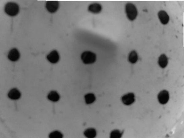
Before the markers can be identified, the authors convert all the undistorted images to binary format, a black and white picture, to achieve a high contrast between the color of the marker and the surrounding area.
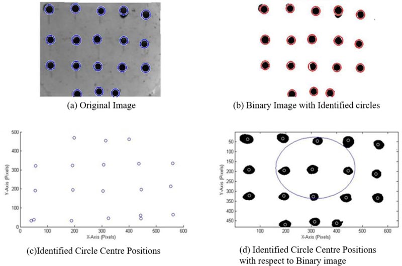
MATLAB R2017a has a function that can identify circles in an image, imfindcircles, which is used in this study to identify the markers. As can be seen in Fig. (6), the markers are inscribed by circles identified by MATLAB. A problem observed with this function is the wrongful identification of multiple circles in areas with a single marker. Therefore the authors have incorporated a function by Elad [32] to remove any overlapping circles. The results are the centers and radiuses, in the number of pixels, of the circles representing the 18 markers on the phantom, as can be seen in Fig. (6).
3.2.5. Measuring Deformation
There are two sets of observations used to determine the amount of deformation that is taking place in the soft tissue during manipulation by the robotic force acquisition device.
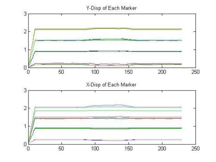
The first is by looking at the displacement of each marker along the x and y axes, separately, over the time period of the experiment, displayed in Fig. (7). The data is based on images recorded by the webcam, which is affected by noise, therefore a moving average filter, with a window size of 10 and a denominator coefficient of 1, is applied to the data.
As seen in Fig. (7), the interaction between the laparoscopic tool model and soft tissue phantom creates a parabolic displacement along the x and y axes, therefore these displacements can be applied to the wave equation in the same form. Through the fitting of a parabolic equation in each direction (x & y), for each marker, and determine the f(x,y) in equation 3. The differences between the different trials were insignificant, therefore, the number of trials was considered to be satisfactory for the consistency of the result.
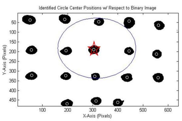
The second displacement is measured with respect to the affected area, which are the nine markers approximately inscribed by a circle in Fig. (8). This area is of interest because the middle marker, marked by a star in Fig. (8) is where the tool interacts with the silicone phantom and is most affected during the deformation. Since it is the most affected marker, it is assumed to be the center vertex with respect to the deformation. The circle fit is determined using a MATLAB function by Bucher [33] and the results are plotted using another function by He [34].
An important part of this stage of the study is the identification of the marker and its position, which is used to determine changes along the xy plane due to the changes along the z axis. A limitation of this segment is the removal of overlapping circles, because imfindcircles can find multiple circles, as seen in Fig. (6), at the position of one marker. The overlap removing function takes an average of all the circles in the vicinity, many of which are errors, and therefore add to the error of the displacements observed in the study. As can be seen in Fig. (6), the markers that are painted onto the phantom are not perfect circles in the binary images, therefore, making it difficult for MATLAB to accurately identify them as a single circle. Along with that, as can be seen in Fig. (9), the markers also deform, which is because they are painted onto the phantom and move with it. Therefore in future studies, it would be beneficial to use markers that move during the deformation but do not change in shape; for example, using solid markers that are attached to the phantom.
As can be seen from Fig. (7), some of the markers have displacements in the positive direction, whereas others are moving in the positive direction with respect to their original position. This is because as the laparoscopic tool pushes down on the soft tissue phantom, the soft tissue stretches in the positive and negative directions along the x-y plane to compensate for the force applied and prevent failure of the material. The parabolic shapes in Fig. (7) are used to fit a parabola to the data and therefore develop an initial displacement function f(x,y). Because all the markers are moving in different directions, some of them cancel out each other when an average of all the parabolic functions is calculated to get the resulting functions. The data used to develop these models is the filtered data due to the amount of noise in the unfiltered data while focusing on the frames with deformations. The r2 for these parabolic fits is an average of 0.89 mm with a maximum of 0.956 mm and a minimum of 0.555 mm. This wide range can be attributed to residual noise associated error.
The circles that are used to model the area of deformation are approximations as they are fitted around the nine markers as shown in Fig. (8). These circles are important because they show the deformation causing the markers to move outward in a circular shape and their return to the original position in the same manner. Therefore the use of circle functions are used to determine the dataset of importance and the area of the affected membrane.
3.3. New Wave Equation
3.3.1. Using Experimental Data to Develop a Wave Equation
The displacements observed in the experimental setup above are used to develop a wave equation, which mimics the behavior of soft tissue phantom in a physical situation, for a more realistic experience in the VR training system. This includes determining the essential data required to develop a two dimensional wave equation that represents the skin’s deformation in response to tool manipulation.
3.3.2. Circular Displacement of Affected Area
The circular displacements of the nine major markers, over time, are used to determine a fit for the circles drawn around them. These displacements are important because they illustrate the movement of the markers during deformation, outwards and then inwards towards their original position, as can be seen in Fig. (10). A circle is used to model the changes in the marker position as that is the shape seen on the surface of the phantom during the interaction in the experimental setup.
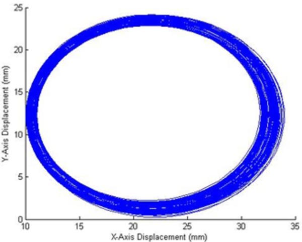
The maximum radius and its location in the time frame of the experiment are used to determine when the maximum deformation takes place in the experimental time frame from which, d, a variable in f(x,y) for the initial displacement in equation 3 is calculated. The maximum radius is also used to determine the boundary conditions of the two dimensional wave equation, as it is the area of deformation in the experiment. The maximum radius is, therefore, when the markers are the furthest from each other due to the manipulation.
3.3.3. New Initial Displacement Equation
In this study, we are assuming that f(x,y), the initial displacement is:
 |
(4) |
where 0(x) and p(y) are parabolas, therefore we can fit a parabola at the marker of interest, along with the respective x and y displacement data, as can be seen from Fig. (7). The assumption that the two functions are parabolas gives us a deformation that looks like half of an ellipsoid. Therefore using the polyfit function in MATLAB, the authors determine the parabolic function within the time period of the deformation and an average of the fits gives the following equation:
 |
(5) |
 |
(6) |
The d in equation 4 is determined using the maximum radius from Fig. (9) to determine the time of complete deformation, at which time the robotic force acquisition device is approximately 0.002m below the starting point on the testing platform. The marker which is used to calculate at this depth and time period, is marked by a star in Fig. (8).
3.3.4. Modeling the New Wave Equation
In this study, silicone is used as a model for soft tissue in the experimental setup, when developing a new wave equation. Silicon elastomers are widely used as skin models because of the mechanical properties, stability and non-toxicity [35]. Therefore, the method employed in the preliminary study by Patel and Suthakorn [22] has been used in this section to develop a new wave equation based on the data collected.
Table 1 lists out all the variables that are calculated using the data collected from the experiment and literature values for the mechanical properties of the skin. These variables are essential for the development of a two dimensional wave equation. These variables create the following equation:
 |
(7) |
Equation 7 is implemented into MATLAB’s MuPAD to create an animation and check the visualization of the new two dimensional wave equation; Fig. (11) is a screenshot from the developed animation and models the chape of the dermis when pushed down by a laparoscopic tool. The unit along the three axes (x,y,z) is millimeters.
The new wave equation demonstrates the modifiability of the two dimensional wave equation to meet the needs of the soft tissue model. Despite the use of a soft tissue phantom, this method can be used to develop a soft tissue model using displacements of the soft tissue during the deformation.
The new wave equation model, which is developed using the experimental data, is animated in this study and shows the ability of the model to display the manipulation that is performed during the experiment. Therefore in the animation, we see the model move down in response to interaction with the laparoscopic tool and return to its original shape upon removal of any external force.
The aim of this study is to mimic the mechanical properties of the soft tissue while limiting the computational cost and increasing the accuracy of the model. This study looks at the development of the mathematical model for the dermis, but this method can also be used to model the other two layers of the skin, epidermis and subcutaneous fat, using the results from the experimental setup, mechanical and material properties of the individual layers.
| Variablesa | Value |
|---|---|
| o(x) | (-8.393 x 10-6)x2 + (0.002)x + 1.3322 |
| p(y) | (-8.1904 x 10-6)x2 + (0.002)x + 0.9876 |
| d | 14.3321 |
| c2 | 85.56 ... c = 9.2496 |
| m | 1 |
| n | 1 |
| a & bb | α = b = 23.6053 |
| λmn | 1.7409 |
| Bmn | Bmn = 39.2012 |
ba and b are the variables that represent the boundary conditions of the membrane in the wave equation. This value is determined by the data points along the x and y axes for the circle, in Fig. (10), with maximum radius.
An assumption that is made, in this study, is that the soft tissue phantom has the same mechanical and material properties as the skin, therefore this model could be improved by incorporating these properties for the silicone, used to model the soft tissue or performing an experiment on the soft tissue of interest; in this case the skin.
3.4. Controlling Wave Equation with User Input in a VR Training System
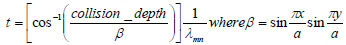
An important part of user interaction is collision detection, therefore this part of the soft tissue model will only be activated if a collision is observed by the system. This collision will result in the deformation of the soft tissue, when interacting with laparoscopic tools. As can be seen from equations 2 and 7, the solution of two dimensional wave equations, which are developed to model soft tissue behavior in a virtual environment, is based on three inputs: x, y, and t. Based on the data listed in Table 1, we know that the x and y boundaries are from 0 to approximately 24 mm, therefore we have a square surface area along which the deformation takes place. Assuming we have a soft tissue mesh with an area of and a vertex at each millimeter, we would like to make sure the deformation takes place in the area manipulated by the user and the deformation size matches the observed values. To achieve this, the authors propose identifying the location of the collision of the tool (the x, y coordinate) and the collision depth. Using these data points as the midpoint of the collision, we determine the behavior of the neighboring vertices in the area mentioned above.
 |
(8) |
This, therefore, is achieved by the reorganization of the solution of the two dimensional wave equation, to use the z (collision depth) along with the x, y coordinates to calculate the time period in the model that the deformation represents, as shown in equation 8. This therefore allows the program to calculate the deformation of the neighboring vertices at the t and accordingly develop a deformation.
The mesh is larger than the soft tissue at hand, therefore, the authors have to translate the deformation with respect to the location of the user manipulation. This translation is achieved by the manipulation of the vertex number because the original model assumes the deformation is taking place from (0-24) mm along the x and y axes. Therefore if the user hits the tissue at (60, 50) mm on the x, y plane, the area of the deformation would be along (48-71) mm along the x axis and (38-61) mm along the y axis, while the rest of the mesh remains unaffected.
In the animation captured in Fig. (11), the soft tissue model only returns to the original shape after the model has reached the maximum depth, but when working with user input, the training system developers have to keep in mind that the user may push the model only half way down after which the tool is removed, therefore, the soft tissue would have to return back to its original shape. This will be achieved by a statement which will order the wave equation to move in the direction of the original shape, when there is no collision between the tool and the soft tissue model. This, therefore requires a determination of the number of steps to return to the original shape, which in this case is when all the vertices are at z=0, and using a for loop this action is achieved.
3.5. Validation Study
The validation is based on the method designed in a previous study by Patel and Suthakorn [22]. Various studies conclude that FEA is one of the most accurate methods of modeling soft tissue or a deformable material, therefore, the model is used as a baseline to evaluate the new heterogeneous representation of skin.
For this study, the FEA setup from the previous study [22] is used and consists of the three layers of skin, similar to the wave equation representation. In this setup, the model is deformed by a force that rises over time until 5N, after which the manipulation is removed until the model returns to its original shape. The same manipulation is modeled using the two dimensional wave equations. Firstly, the maximum deformation is found for the FEA model. Then, the value is inputted into the heterogeneous wave equation model to see whether the same deformation value is outputted by the function.
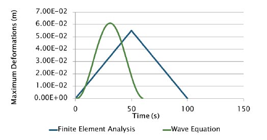
The computation time for the FEA model is 4 minutes, whereas the heterogeneous wave equation was solved in 10 seconds. The results are analyzed using two statistical methods, which are normal distribution and two-sample t-test (Table 2), which are used to determine whether the FEA and wave equation heterogeneous models are similar, which is expected as they both model the same soft tissue, the skin.
| - | FEA | Wave Equation |
| Mean | -0.05508 | -0.05509 |
| Variance | 0.001022 | 0.001023 |
| Observations | 100 | 100 |
| Hypothesized Mean Difference | 0 | - |
| P(T<=t) two-tail | 0.997171 | - |
| t Stat | 0.00355 | - |
| t Critical two-tail | 1.972017 | - |
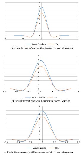
Fig. (12) shows the comparison between the FEA model and the heterogeneous wave equation model from the perspective of the maximum deformation. Similarly, Fig. (13) illustrates the normal distribution that compares the results from both models. The results have been classified on the basis of the tissue types: epidermis, dermis and subcutaneous fat. As can be seen from the plots (Figs. 12 and 13), the deformations are very similar, but they are not equal with an average percent error of 0.089%.
4. DISCUSSION
This soft tissue model is developed for application to a VR surgical training system, with a focus on laparoscopic skills because of the unique psychomotor skills required in these procedures. This system is aimed to assist young and inexperienced surgeons and provide them with a training environment which allows repetitive and intensive training with limited expert supervision required. This system can also be used by experienced surgeons to plan complex surgeries with patient/procedure specific models. The system will consist of a graphical user interface (GUI) with the proposed soft tissue model, and user interaction through two haptic devices that represent the two laparscopic tools; in this case, the authors will use two Phantom Omnis which can output force feedback based on an input of positions.
4.1. Heterogeneous Material: Skin
An important aspect of this soft tissue model is the ability to model the different layers of soft tissue and therefore develop a heterogeneous model. Even though this study only shows the method to develop a model for the dermis, the procedure can be used to model the different layers of the skin. In previous studies, the authors divided the skin into three layers: epidermis, dermis and subcutaneous fat [22]. To apply the experimental results to each of the layers, the data from the phantom maker displacement can be applied to different layers of the skin by applying the respective properties when developing the two-dimensional wave equation. The displacement data from this experiment is used for multiple layers of the skin because the phantom represents the skin and this study assumes that the layers of a soft tissue move together during manipulation to form the resulting deformation.
Along with that, in the GUI, the skin will be modeled using multiple blocks, representing the thickness and material properties of each of the layers of the skin at hand. Therefore, the two-dimensional wave equation for each of the layers of the skin will be applied to the respective block. The three blocks, representing the layers of skin, are mated with each other and will work together during the manipulation. This distinctive separation of the soft tissue layer would allow the user to also experience the distinctive mechanical properties of the layers during interaction, for example, the changes in force output when penetrating different layers of the soft tissue.
4.2. User Interaction with GUI
This study not only allows the collection of data important for mimicking the deformation of the soft tissue during a manipulation but also collects force data; therefore, the new training system can use this data to output the force that the user experiences according to the deformation of the soft tissue model. The force data collected along the z-axis is of interest because the direction of manipulation is along the z-axis and the force in this direction is up to three significant figures higher. This, therefore, will be associated with the collision depth data collected from the experimental setup and the respective force measured during the experiment. The input received from the Phantom Omni is the position that will be an input for the deformation and the force feedback.
4.3. Objective Performance Assessment
Another important aspect of the VR training system is its ability to provide the user with an objective performance assessment to determine when a young surgeon is ready to operate on a patient [36-39]. This part of the VR training system is used in various studies as a method of construct validity to determine the user interface as an effective training system or to observe the system’s ability to differentiate between an expert and a novice user [40-43].
The Phantom Omni, a haptic device, provides the virtual environment with position data of the tool, which is controlled by the user, whereas the software of the user interface can be utilized to measure the time to complete the task or procedure at hand. Using these datasets, the training system can objectively evaluate the user’s performance in the training system using metrics like: time to task completion, path length, smoothness of movement, and bimanual dexterity [36, 44].
CONCLUSION
This study looks at VR training systems for laparoscopic surgeries to improve skills and performance in these procedures of novice surgeons. This study focuses on the soft tissue models that are used in these training systems, with the aim to mimic the visual behavior of soft tissue in response to manipulations by laparoscopic tools. Therefore, the authors suggest the use of physical models of soft tissue to observe the behavior of the soft tissue in a simple interaction with a laparoscopic tool. Using data from these experiments, the authors have developed a two-dimensional wave equation. This wave equation will be implemented in a new VR training system, with the goal to provide doctors with intensive and repetitive training.
ETHICS APPROVAL AND CONSENT TO PARTICIPATE
Not applicable.
HUMAN AND ANIMAL RIGHTS
Not applicable.
CONSENT FOR PUBLICATION
Not applicable.
AVAILABILITY OF DATA AND MATERIALS
The datasets generated during the current study are available from the corresponding author on reasonable request.
FUNDING
This research has been funded by the Computer-Integrated Intelligent Medical System Project under the National Research University Grant through Mahidol University. Another fund resource is the Integration of Surgical Navigation and Surgical Robotics for Breast Biopsy in Breast Cancer using Mammogram and Ultrasound Images on Breast Mathematical Model Project under the Government Research Budget through Mahidol University (Grant no. 111-2558), Thailand.
CONFLICT OF INTEREST
The authors of this paper have no conflict of interest or financial ties to disclose.
ACKNOWLEDGEMENTS
The authors would like to thank Prof. Chumpon Wilasrusmee, M.D., R.N., from Ramathibodi Hospital, Mahidol University, for his continued assistance and guidance throughout the development of a novel virtual reality laparoscopic surgery training system. The authors would also like to thank BART LAB’s Miss Nantida Nillahoot, [17], for her design of the Force Acquisition Robotics System for Percutaneous Needle Insertion, modified by Miss Tanyaporn Pungrasmi and Miss Pavinee Jaturapisanukul, which is used to manipulate the soft tissue in this study.
S. Patel would like to take this opportunity to thank Aditya Birla Group’s Pratibha Scholarship, and Biomedical Engineering Scholarship (BMES) from the Department of Biomedical Engineering, Mahidol University, for their financial aids towards her graduate endeavors. Additionally, she would like to thank her colleagues at BART LAB for their assistance throughout her research.