All published articles of this journal are available on ScienceDirect.

Overlapping Versus “Kissing” Plates in Femur: A FEM Study
Abstract
Introduction:
The progressively aging population makes higher the probability of operate fractures in patients who have underwent past long bones fixation. Surgeons may consider not to remove the past implant because of poor bone quality and low life expectancy, but attention must be paid to avoid the origin of new dangerous stresses. There is still a lack of evidence in determining which is the best relation between a plate already implanted in the past and a new fixation device.
Objective:
The purpose of this study was to investigate how the bone-implant stress distribution changes with two different plate configurations: overlapped (the tip of new plate covering part of the old one) versus “kissing” (the tips of the plates in close contact).
This study was based on a finite element analysis by means of Rhinoceros® and Ansys Work bench software programs. In order to reduce confusing factors, the femur was considered to be not fractured.
Materials & Methods:
Different features have been tested: bone quality, plate materials, and plate configurations. The study was conducted by evaluating stress values in different femur sections. The same parameters were evaluated in a femur without plates. Three phases of gait were simulated: Heel-strike, midstance, and toe-off.
Results:
Heel-strike phase has shown to reach the highest stresses. In general, stresses are lower in the overlapping plates configuration when compared to the “kissing” plates one.
Conlusion:
The main evidence shown in this study is that, in silico, the overlapped configuration can decrease the stress under the plates intersection, without increasing the stress shielding.
1. INTRODUCTION
The knowledge of the mechanical characteristics of bone tissue and of the whole bone elements, particularly regarding its behavior under load, is without doubt fundamental for studying it in various physiological and pathological conditions, looking for substitution materials, and for investigating possibilities of coupling with other materials and devices.
The structural analysis of skeletal body elements and of the biomechanical systems consisting of a bone element coupled with a prosthesis, an implant or a fracture synthesis device can be performed both numerically and experimentally. There are many examples of clinical problems that have passed from a qualitative assessment to a quantitative evaluation thanks to their modeling [1-7] or to the application of classical experimental methods of structural analysis both whole-field [8-10] and punctual techniques [11]. Every approach has its own limitations: numerical models can be very complex and consequently need to be validated; experimental tests cannot faithfully reproduce the real conditions and mostly require simplifications. On the basis of these assumptions, both approaches still remain necessary and complementary.
In this work, we decided to use a finite element numerical model to clarify a couple of intervention methodologies related to a particular case of femoral bone fracture.
Fractures are becoming more common with the ageing of population. This has led to an increasing number of patients who has undergone internal fixation in the past.
Osteoporotic bone has a decreased healing capacity and a higher rate of implant failure [12-14]. The bone fragility is the consequence of both excessive bone resorption and inadequate formation response (quantitative changes) and micro architectural deterioration (qualitative changes) of the skeleton resulting in decreased bone mass [15]. The interface between the tip of the plate and the bone is an area in which a stress peak occurs and may lead to peri-plate fracture [16]. Elderly people are more likely to fall [17]. Predisposition to falls combined to bone fragility represents a high risk for peri-implant failures.
Peri-implant failures of the femur are mostly reported around the metallic devices (nails and plates) [18]. When a plate is applied to the bone, the stiffness of the plated sections is higher than the other ones of the bone and there is an abrupt transition from the bone interfaced with a plate and the free bone that causes a stress raise. The interface between the tip of the plate and the bone is a likely fracture site [16].
Conventional plates base their stability on rubbing with the bone surface. Traditional non-locking screws are susceptible to pull out, especially when put into osteoporotic bones [19].
Locking constructs can overcome this disadvantage because stability is achieved through the solid stability between plate and screws [20]. This is recommended for the treatment of osteoporotic fractures [21].
A clinical dilemma emerges in the treatment of femur fractures where a plate is already present. The best setting when dealing with plate fixation and another plate is already in place in the same bone is questionable.
This becomes a technical issue when treating femur fractures by means of ORIF (Open Reduction and Internal Fixation) in patients with a history of past plate fixation, and it is still a challenging surgical problem.
There is a lack of reports in the literature, especially when the old device removal is not advisable (strong bone integration, risk of bone demolition, probable excessive bleeding, too aggressive surgical approach in relation to patient, general conditions, limited life expectancy). Despite the clinical considerations, the mechanical goal is avoiding the generation of new stress raises, where new ruptures can arise.
The primary objective of this study was the investigation of a better and safer model of intervention, especially when conditions force the surgeon to insert a plate where an old one is already present, and not removable.
We hypothesized that overlapping the end of the new plate partially over the old one would minimize localized stresses. The purpose of this study was to determine how the bone-implant stress distribution changes with different plate configurations: overlapped terminal ends of the plates versus “kissing” (the tips of the plates next to each other).
2. MATERIALS AND METHODS
In this study, we used a numerical model of a femur [22] starting from a CAD model of a Sawbones Femur (Sawbones®, Vashon Island, WA, USA), whose shaft is 316 mm long, suitably modified for our aim by means of CAD software Rhinoceros V5.0 (Robert McNeel & Associates, USA).
The femur was divided by anatomical zone: Head, Neck, Trochanter, Cortical diaphysis, Trabecular diaphysis, Condyles.
The models of the plates (8 and 12 holes), shaped by CAD software Rhinoceros V5.0 (Robert McNeel & Associates, USA), were based on 4.5 mm Synthes LCP (Locking Compression Plate) (DePuy Synthes, Synthes GmbH, Switzerland) (but they are not just the same plates). These plates were chosen because of their widespread availability.
Plates thickness is 4.6 mm and width is 13.5 mm; the 8-hole plate is 152 mm long, while the 12-hole plate is 224 mm long.
Screws diameter is 4.5 mm. Screws lengths are different in different parts of the femur in order to get a bicortical fixation.
Screws thread was omitted to make simulation simpler. Plate and screws heads were assumed to be in-built. Screws pull out occurrence was omitted as irrelevant for the present study purpose.
2.1. Finite Element Method (FEM) Model
Two plates were hypothesized to be implanted in the same femur on the lateral side.
Different features, concerning bone quality (healthy and osteoporotic bone), plate materials (stainless steel and titanium alloy) and plate configurations (overlapped and “kissing”) were simulated.
In order to reduce confusing factors, the femur was considered to be not fractured.
The study was conducted by means of Ansys Work bench V14.5 software program (Ansys Inc., USA) by evaluating average stresses values (compression, tension) in five different sections of the femur among which at the proximal tip of the proximal plate, the middle section where plates are in close proximity or overlapped and at the distal tip of the distal plate.
The same parameters were evaluated in a femur without plates.
2.2. Material Properties
All materials were considered isotropic and homogenous with linear elastic behavior.
The distinction between cortical and trabecular bone was chosen differently considering shaft and epiphyses. As the shaft characteristics are among the main features of this study, cortical and trabecular bone was precisely divided in this area.
In the other parts (head, neck, trochanters and condyles) mechanical properties result as the average value of the cortical and the trabecular bone considered together.
Properties of different femur regions are showed in Tables 1a and 1b [23].
Osteoporotic bone was defined by its density (-50%) and its Young’s modulus (-33% for the cortical bone, -66% for the trabecular bone) when compared to healthy bone [23].
Titanium alloy and stainless steel are widely used in plates and screws production because of their mechanical properties, biocompatibility and resistance to corrosion. When hypothesizing a fixation pattern, this was always assumed homogeneous (both titanium alloy or stainless steel plates in the same femur): Indeed, in vivo fixations can be non-homogeneous. Properties of these materials are shown in Table 2.
2.3. Mesh
The quality of the simulation is determined by the Quality Mesh indicator (QM) [24]. Mesh optimization was done on some parts of the model where the study was focused on and where the shape of the model was very specific (i.e. the turning edges of the screw holes). Other parts, like the flat surface of the plate, anyway relevant, but less demanding in terms of modeling, requested a lower refinement.
2.4. Loads and Boundary Conditions
The gait, as a convention, was divided into three phases, to test the model in three different static load conditions: Heel-strike, Midstance, and Toe-off.
The heel-strike phase is when the foot touches the ground and when the body weight is put on the single limb. The second phase is the midstance. These first two stages cause a quick raise in stress to the limb. Then, when the foot detaches from the ground, it follows the toe-off.
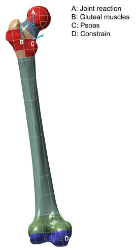
Joint and muscular forces were simulated in accordance with the simplified model suggested by Lotz et al. [23]. The muscles considered are respectively gluteus maximus, medius and minimus, psoas. Loads considered, varying in the three gait phases, were determined multiplying body mass (a hypothetical standard 75 kg heavy person) by a coefficient and transforming it in a force [N] considering the acceleration due to gravity (Table 3). The condyles were fully constrained (Fig. 1).
| Healthy Femur | |||
|---|---|---|---|
| Femur Region | Young’s Modulus [MPa] | Density [kg/m3] | Poisson’s Ratio |
| Head | 9.00E + 02 | 800 | 0.29 |
| Neck | 6.20E + 02 | 800 | 0.29 |
| Trochanter | 4.00E + 02 | 800 | 0.29 |
| Condyles | 4.00E + 02 | 800 | 0.29 |
| Osteoporotic femur | |||
| Head | 6.12E + 02 | 400 | 0.29 |
| Neck | 4.21E + 02 | 400 | 0.29 |
| Trochanter | 2.72E + 02 | 400 | 0.29 |
| Condyles | 4.00E + 02 | 400 | 0.29 |
| Healthy Femur | ||||||
|---|---|---|---|---|---|---|
| Cortical Diaphysis | Trabecular Diaphysis | |||||
| Young’s Modulus [MPa] | Density [kg/m3] | Poisson’s Ratio | Young’s Modulus [MPa] | Density [kg/m3] | Poisson’s Ratio | |
| 1,67E + 04 | 1750 | 0.29 | 5.00E + 03 | 1000 | 0.29 | |
| Osteoporotic Femur | ||||||
| Cortical Diaphysis | Trabecular Diaphysis | |||||
| 1,13E + 04 | 875 | 0.29 | 1.70E + 03 | 400 | 0.29 | |
| - | Young’s Modulus [GPa] | Density [kg/m3] | Poisson’s Ratio |
|---|---|---|---|
| Stainless steel | 193 | 7750 | 0.31 |
| Titanium alloy | 96 | 4620 | 0.36 |
| Muscle | Heel-Strike | One-legged Midstance | Toe-Off |
|---|---|---|---|
| Gluteus Maximus | 0.64 | - | - |
| Gluteus Medius | 0.62 | 2.60 | 0.55 |
| Gluteus Minimus | 0.54 | - | 0.61 |
| Psoas | - | - | 0.65 |
| Joint load | 4.2 | 1.80 | 3.90 |
Summarizing, the structural analysis was performed for:
- Three possible femur conditions:
• Not fractured without any plates
• Not fractured with two “kissing” plates
• Not fractured with two overlapped plates.
- Two supposed bone structures, healthy or osteoporotic.
- Two plates materials, stainless steel or titanium alloy.
Overall ten different configurations (healthy or osteoporotic femurs, with or without plates, kissing or overlapped, stainless steel or titanium alloy plates) were examined in the three different walk phases (heel-strike, one legged midstance, and toe-off).
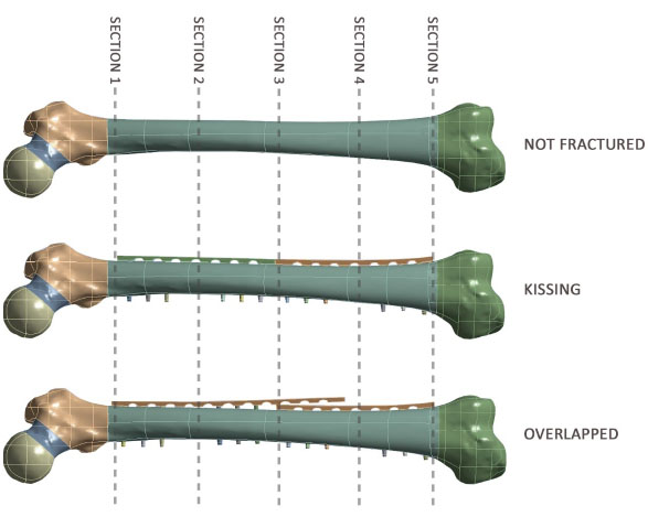
For all the configurations, stress values were evaluated in five cross sectional areas (Fig. 2).
3. RESULTS AND DISCUSSION
The heel-strike phase was emphasized because of its higher stress values obtained. Toe-off load case results were comparable with those of heel-strike phase, while one legged midstance case stresses resulted anyway lower.
Results obtained for heel-strike phase are summarized in (Fig. 3), which shows, respectively, tension and compression average stresses in the five bone sections along the anatomical diaphyseal axis (σz in this study).
The main evidence is that both tension and compression stresses in middle section (section 3) are lower in the overlapped plates configuration when compared to the “kissing” plates configuration, but this difference is more pronounced for tension stresses.
It is also evident that the trend along the diaphyseal axis of the femur (orange lines) is more homogeneous in the case of the overlapped configuration, both for tension stresses and for compression stresses, that is in this case the highest stress discontinuities are concentrated only at the tips, respectively proximal and distal, of the two plates, near the epiphyses, where, moreover, the values of the stresses are of the same order of magnitude as those obtained with the femur without plates.
In both configurations stresses trends along the diaphysis deviate from stresses trends obtained with the femur without plates, in particular in correspondence with sections 2, 3 and 4. However, this deviation is more constant in the case of the overlapped configuration with respect to the “kissing” configuration.
With the same geometry, stainless steel plates are stiffer than the titanium alloy plates and that causes, in both configurations, a bone stress reduction more accentuated, compared to the physiological situation, in correspondence with sections 2 and 4; this situation is particularly evident for the tension stresses and when the bone is osteoporotic.

Femoral fractures in elderly patients with a history of plate fixation for remote fractures is getting more and more frequent. The optimum would be a plate removal and a totally new synthesis, but this cannot be always performed, sometimes because of a tough bone integration, if a too aggressive surgical approach would be needed, sometimes when the fixation device has been in place for a too short time. Therefore, a clinical dilemma became striking: what should the relationship be between the new plate and the old one?
In young patients and athletes, hardware removal is recommended for the high risk of future fracture in proximity to plates or nails [25, 26].
Cadaveric studies have demonstrated that locking plates have an improved mechanical performance in torsional cycling loading over non locking constructs, especially in osteoporotic bone [27, 28].
We undertook this study to determine how the bone-implant stress distribution changes with two different plate configurations: overlapped (the tip of new plate covering part of the old one) versus “kissing” (the tips of the plates in close contact).
A study [29] showed the effectiveness of this technique for the treatment of not healed peri-plate fractures in elderly osteoporotic patients by using clinical trials. The result is that a solid fusion can be achieved at the new fracture site without the need to disturb the previous fracture fixation. This method also decreases the morbidity of the peri-plate fracture surgery since the approach is limited to the new fracture area without the need to access the preexisting plate-fracture site. The trial was based on a sample of three female patients aged between 55 and 93 years; the sample is not statistically significant but highlights the potentiality of this approach.
The femur can be considered a good model in studying long bones considering a generic old population and it has often been analyzed as the reference point in studying the long bone fracture healing process [13].
For all the configurations, the tension stress values are evaluated in cross sectional areas that in vivo can be the zones where fractures are more likely to happen.
Two different plate materials were considered, stainless steel and titanium alloy. Many studies assert that bone-like stiffness materials promote healing [30], so titanium alloy plates should be more physiological and results obtained confirm it.
Nevertheless the material of the new plate may differ from the preexisting one and this should not affect bone healing, quality of fixation and stability since recent reports showed that stainless steel and titanium alloy fixation devices can be mixed without any significant complication [31].
The maximum tension stress reached for the load that simulates heel-strike phase is about 65 MPa. Typically, the yield stress for the bone material is around 80-85 MPa and the Ultimate Tensile Strength is around 120 MPa [32]. Other authors report that cortical bone tensile yield stress is between about 80 MPa and 150 MPa including osteoporotic bone [33]. In this simplified simulation, the focus was not to check the absolute stresses values but to investigate their distribution.
The simplifications assumed in the work, only one single load type has been considered, that although the most frequent is not the most demanding for the femur, homogeneous and isotropic behavior of bone, are justified by its comparative purpose.
CONCLUSION
The evidence that comes from this study is that stresses in the long bones diaphysis in the middle section (section 3) were higher in the “kissing” plates configuration and that they could be reduced if the new plate is put for a short portion over the old one. The overlapped plates configuration allows to better distribute stresses on the bone region between plates ends. The stress peak in the middle section, that is evident in the “kissing” configuration, disappears, nevertheless stress is not eliminated, in fact it is important that stress does not reach a value too low compared to physiological one, under the overlapped plates limiting the stress shielding and preventing the consequent bone resorption [34, 35]. We can speculate that results depend on the capability of the two overlapped plates of working together as an elastic damper, like leaf springs in old cars. Probably variables like plates dimensions (width, length, thickness), materials, friction forces between the plates and between the plates and the bone, the strength in screws tightening and the amount of overlapping play a role in the stresses reduction.
Although the peak of stress reached in the middle section area in the kissing configuration does not reach failure values, it warns about the increase possibility of a re-fracture in this area.
In the clinical setting the patient presents a fracture that is already healed under the old plate and a new fracture that is starting its healing process under the new plate. The problem to the surgeon, from this perspective, is not controlling the fracture healing process, but not to create a new one at the plate crossing point.
In conclusion, fractures around implants, very frequent in elderly patients, force surgeons to a better understatement of the bone behavior in proximity and under plates. Surgeons may consider not to remove the implant because of the poor bone quality and low life expectancy.
The main evidence we showed is that, in silico, an overlapped plates configuration, compared with a “kissing” plates one, even if greatly reduces the state of stress in the bone, especially in tension, it allows a homogeneous stress distribution avoiding large discontinuities that notoriously the bone does not like.
Some features remain to be studied and we look forward for other experimental and clinical in vivo studies to produce well defined guidelines.
CONSENT FOR PUBLICATION
Not applicable.
AVAILABILITY OF DATA AND MATERIALS
The data that support the findings of this study are available from the corresponding author, [C . Bignardi], upon reasonable request.
FUNDING
None.
CONFLICT OF INTEREST
This work was done at the Department of Orthopaedics and Traumatology, Orthopaedic and Trauma Center, Azienda Ospedaliera Universitaria Città della Salute e della Scienza di Torino and at the Department of Mechanical and Aerospace Engineering (DIMEAS), Politecnico di Torino, Torino, Italy.
Each author certifies that he or she has no commercial associations (e.g, consultancies, stock ownership, equity interest, patent/licensing arrangements, etc.) that might pose a conflict of interest in connection with the submitted article.
ACKNOWLEDGEMENTS
We thank Alex Trumble for his precious assistance.