All published articles of this journal are available on ScienceDirect.

Modeling of Drug Delivery by A Pump Driven Micro-Needle Array System
Abstract
Background:
Micro-needles were proposed as one of the alternatives to deliver drugs painlessly passing through stratum corneum in recent years. In this work, a mathematical model is presented to characterize the in fusion flow of a hollow micro-needle array driven by a micro-pump.
Methods:
By assuming the injection of each micro-needle undergoes a spherical expansion and diffusion, the model is able to calculate the time-varying expansion radius, and the diffusion boundary, provided that the material properties and the micro-needle system parameters are known.
Results and Conclusion:
The calculation results show that the expansion caused by the infusion of micro-needles stops and the flow rate drops to zero in a short time. However, the diffusion boundary is much bigger than the expansion and the infusion continues if the surrounding material is absorptive. The experimental results of jet infusion through a single needle in silicon rubber and polyacrylamide gel agree with the calculation results qualitatively.
1. INTRODUCTION
Although patch-based transdermal drug delivery has been used for clinical application over decades, it faces the challenge of overcoming stratum corneum as a natural barrier to large molecular drugs. Other physical or chemical enhancing methods are inconvenient and rarely used in practice. Ordinary sized needles are associated with problems such as pain, trauma, bleeding, etc. Micro-needle array, a technology having both the non invasive feature of a drug patch and the effectiveness of a hypodermic needle, has been reported to increase the drug permeability in skin by several orders of magnitude [1, 2]. Solid micro-needles were first fabricated from microelectronic industry in 1980s, and are often coated with drugs for rapid bolus administration. Hollow micro-needles were fabricated using a silicon nitride shell on top of a silicon substrate subsequently. They are often combined with a micro pump or a syringe to create a controlled drug delivery system [1, 2]. The micro-needle system can also be integrated with other techniques such as optical trapping, to trap, store and deliver drug molecules/cells to specific targets [3]. Through decades of research, different techniques have been developed and improved for the fabrication of micro-needle array that originates from microelectronics industry [4-7]. A dissolvable polymer material was proposed for the fabrication of a micro-needle patch. The new micro-needles can be dissolved into bodily fluid after being pierced into the skin [8, 9].
Lots of investigation has been done to understand physical mechanism involved in the injection of micro-needle delivery, in order to optimize the system variables and improve the performance of the micro-needle transdermal delivery. Sanders et al. [10] developed constitutive models that describe skin response to stretching force. Kong and Wu [11] studied the penetration of a sharp tip into human skin. Gomaa et al. [12] studied the effects of micro-needle length, density, insertion time on enhancing drug flux through measurements of trans epidermal water loss. The propagation of drug after its initial infusion has been studied by Lv et al. [13] and Zhang et al. [14]. Recent research found that achieving larger flow rates has been difficult, apparently due to the low flow conductivity in the skin, and the compression of dense dermal tissue during micro-needle insertion, which increases the resistance to flow [15, 16]. However, micro jets interaction with the skin and the jet behavior under the skin have not been fully understood. Theoretical models so far mostly focus on the piecing process for solid micro-needles [17]. Shergold & Fleck [18] developed a micromechanical model for the needle penetration of a soft solid. The authors have developed an analytic model based on liquid expansion in a soft solid to calculate the initial infusion of a micro-needle array driven by a micro-pump [19].
Ideally, hollow micro-needles shall have more clinical applications than solid micro-needles for its feature of continuous and controlled drug release. However, it has generally received less attention and has been less used due to its practical problems. Most studies on hollow micro-needles were of in vitro experimental performance. There are currently few theoretical models developed that can describe the flow behavior of the micro jets inside the skin. Our previous study has presented an analytic model based on the liquid expansion in a soft solid for the initial infusion of the drug through a micro-needle system [19]. The model assumes that the soft solid is an incompressible, hyperelastic, isotropic material, and the amount of energy delivered by the micro-pump is equal to the energy used for the expansion of soft skin due to micro-needle drug infusion. However, the human skin, especially dermis structure underneath the epidermis is a non homogeneous porous material. The process of liquid diffusion will be dominant after the initial expansion process during the injection of micro-needle system. The presented model consists of two parts: an expansion part and a diffusion part. The diffusion part is based on the mass conservation, and the soft tissue is treated as uniform porous medium with uniform properties. The analytic model can be described by a set of ordinary differential equations. Numerical solutions to these coupled equations are obtained. For a typical commercial piezoelectric micro pump, the flow expansion stops instantly and the flow rate quickly drops to zero, unless the pressure from the micro-pump is increased. If the jet flow rate remains constant, the diameter of the diffusion boundary first increases and then tapes off as a constant, indicating the diffusion process keeps going. Preliminary experiments of micro-needle injection on silicon rubber and polyacrylamide gel were carried out, revealing some qualitative results that match with the results from the modeling work. The present study may shed light on the optimization of the micro-needle system.
2. DESCRIPTION OF MATHEMATICAL MODEL
2.1. General Conservation of Mass and Energy
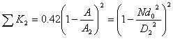
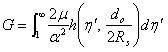
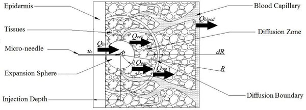
As shown in Fig. (1), a typical hollow micro-needle drug delivery system consists of a drug reservoir, a micro-pump, and a micro-needle array. The micro-needles just pierce across epidermis to produce micro sized channels for further infusion of the drug. The energy used to cause drug infusion and expansion in skin should be equal to the energy delivered by the micro-needles. However, part of the energy provided by the micro-pump is lost due to the minor and major losses in the flow system.
The following expression is obtained after the conservation of energy is applied for the flow system [20].
 |
(1) |
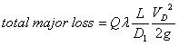
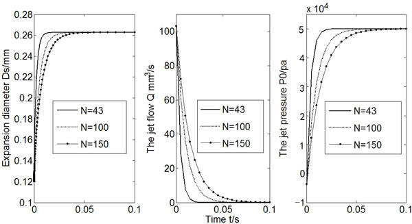
where ρ is the liquid density, V is the liquid velocity, Q is the liquid flow rate from the output of the micro pump, and g is the gravitational constant, Z is the vertical position, Ppump is the pressure that the micro-pump could raise. The subscripts in and out denote the inlet (drug reservoir) and outlet (micro-needles), respectively. The above expression assumes each micro-needle has the same output parameters. The total major loss due to friction in the tube is:
 |
(2) |
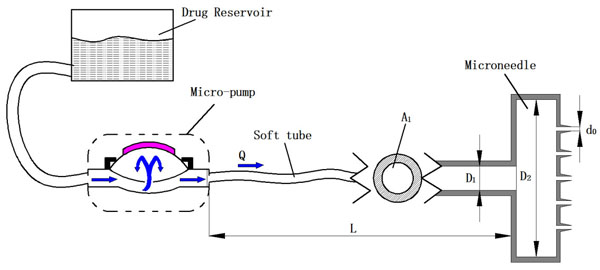
A pump driven micro-needle drug delivery system.
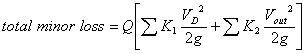
where VD is the flow velocity in the soft tube, D1 is the inner diameter of the soft tube, L is the length of the soft tube, and λ is the friction factor. The total minor loss due to sudden expansion or contractions is:
 |
(3) |
where
 is the total minor loss coefficient that liquid sustains before it flows into the micro-needles, and
 is the total minor loss coefficient of flow in the micro-needle section. Obviously,
 , and
, and
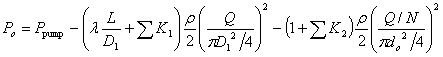
 , where do is the diameter of a single micro-needle on the array, and N is the total number of micro-needles on the array. By changing the notation of Pout to Po, the actual energy that micro-needle can deliver is:
 |
(4) |
Friction factor λ depends upon the viscosity, the state of the flow and the wall smoothness of micro-needles.
and
can be estimated by the following formula [20]:
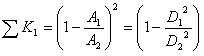 |
(5) |
and
 |
(6) |
where A1, A2 and A are the cross sectional area of soft tube, intracavity of micro-needle array, and micro-needles, respectively. D2 is the diameter of micro-needle intracavity as shown in Fig. (1).
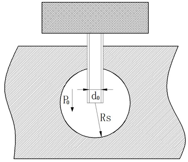
Liquid expansion of single micro-needle in a soft solid.
2.2. The Model of Spherical Expansion
Due to the relatively higher pressure, the liquid coming out of the micro-needle will push the soft skin aside to form an expansion, as shown in Fig. (2). It is assumed in the current model that the initial liquid infusion through a micro-needle follows a spherical pattern of expansion. The mass and energy should be conserved in the liquid infusion process.
For incompressible liquid, the conservation of mass yields:
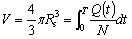 |
(7) |
where V is the volume of total drug delivered from the beginning of infusion through time T for a single micro-needle; Q(t)/N is the volume flow rate of a single micro-needle; Rs is the expansion radius through time T.
From the expansion model given by Shergold & Fleck [18], the work done by the injected liquid through a single micro-needle is equivalent to the stored strain energy in the infinite medium of soft material:
 |
(8) |
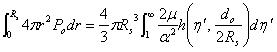
where Po is the liquid pressure coming out of a micro-needle, as described in Equation (4), and r is the radius of the sphere during expansion. α is a strain hardening exponent, μ is the shear modulus under infinitesimal straining of the soft material. η', a dimensionless number, and the function h(), are explained in [19]. If the integration part of the R.H.S is noted as
 |
(9) |
The following equation can be derived
 |
(10) |
The unknown variables Po, Rs can be calculated through Equation (4) and (10), if the micro-pump variables (Pmax and Q), the variables of micro-needle system (N and D1, D2, do) and mechanical properties of soft material (α and μ) are provided.
2.3. The Model of Spherical Diffusion
In addition to expansion, the drug solution diffuses into the skin due to its concentration gradient and natural flow between soft tissues, as shown in Fig. (3). The drug absorption along its flow path gradually decreases. For simplicity, the surrounding tissues are divided into “Saturated Tissues” and “Unsaturated Tissues” by an imaginary diffusion boundary. Within the spherical space inside the moving interface of diffusion boundary, the solution is saturated anywhere at anytime, whereas outside the diffusion boundary the concentration of the drug solution is unsaturated [13].
The diffusion model of single micro-needle in the skin after expansion.
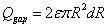
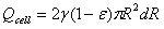
Similar to the model proposed by Lv, et al., the following four parts contribute to the diffusion of drug solution into the skin: The first part is absorption of the tissue cells (represented by Qcell in flow volume), with an absorption rate defined as γ. The second part is taken away by blood vessels (represented by Qblood in flow volume), which is proportional to the total volume by a proportion coefficient expressed as β. The third part is the solution that fills the spaces between the tissues (represented by Qgap in flow volume), which is also proportional to the total volume by a volumetric porosity ε. The fourth part is the drug diffusion through concentration gradient through the diffusion boundary (represented by Qdiffusion in flow volume).
The flow volume of drug solution into the skin during a time period of dt can be expressed as:
 |
(11) |
The four parts of the diffusion of the drug solution can be expressed as:
 |
(12) |
 |
(13) |
 |
(14) |
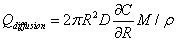 |
(15) |
Where R is the radius of diffusion boundary, D is the diffusion coefficient of the drug solution in the skin, C is the concentration of the drug solution, ρ(kg/m3) is the density of the drug solution, and M (g/mol) is the molar mass of drug solution. The following equation can be obtained from the conservation of mass flow:
 |
(16) |
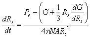
The concentration gradient ∂C/∂R is very small close to the boundary, and the diffusion coefficient D is also very small. dR·dt is a much smaller term than dt or dR. The above equation can be simplified as:
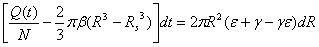 |
(17) |
Again, the diffusion boundary R can be calculated if the micro-pump performance (Q), the variables of micro-needle system (N) and mechanical properties of the skin material (β, ε, and γ) are provided.
3. CALCULATION RESULTS
The coupled equations (Equation (4), and (10)) for the expansion model of the micro-needle drug delivery system derived in the previous section are numerically solved by a Runge-Kutta integration method.
The human skin is generally a highly organized, stratified structure mainly consisting of four layers: the stratum corneum (SC), epidermis, dermis and hypodermis. Ideally, the micro-needles penetrate the SC and reach the viable epidermis or hypodermis for painless injection. Gerling and Thomas [21] presented the mechanical properties of skin as a Young’s Modulus of 1.36×10⁵ Pa for the epidermis, 8.0×10⁴ Pa for the dermis, 3.4×10⁴ Pa for the subcutaneous fat with a Poisson’s Ratio of 0.48 for each layer. The shear modulus (μ) can be thus calculated according to the relationship:
 |
(18) |
where E is Young’s modulus, ν is poisson’s ratio.
For a typical micro-pump of piezoelectric diaphragm type, Q and Ppump follow the reverse linear relationship, that is:
 |
(19) |
where Pmax and Qmax are pump characteristics provided by the manufacturer. A piezoelectric micro pump provided by Bartels Mikrotechnik was chosen for the calculation. For its MP6 pump, Pmax = 550 mbar, Qmax = 6 ml/min, and the inner diameter and the length of soft tube are set at 1.3 mm and 500 mm respectively, and thus, A1 = 1.33 mm2. It is also assumed that the diameter of micro-needle chamber is constant (D2 = 11 mm), and thus A2 = 95 mm2. A= do2/ 4 is dependent upon the inner diameter of micro-needle (do). For the selected pump, the friction factor λ is estimated in the range of 0.6~1.0. For further simplification of calculation, a fixed number of λ = 0.8 was used in calculation.
In order to evaluate the effects of soft material properties and micro-needle system parameters on injection flow characteristics, four groups of calculation were carried out: 1): different strain hardening exponent (α); 2): different shear modulus (μ); 3): different total number of micro-needle array (N); and 4): different diameter of micro-needle (do). The values of α and μ were chosen around the aforementioned values given by [22]. In each calculation, one input variable was changed while others were kept constants. The chosen input variables for the four runs are listed in Table 1.
The system parameters used in the expansion model calculation.
| Diameter do (mm) |
Number (N) |
Shear modulus µ (Pa x104) |
Strain hardening exponent α |
Maximal pressure Pmax (Pa x104) |
Maximal flow rate Qmax (ml/min) |
|---|---|---|---|---|---|
| 120 | 43 | 1.1 | 6 | 5.5 | 6 |
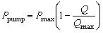
The results of Ds (2Rs, expansion diameter), Q (flow rate) and Po (expansion pressure) varying with time for three different α values were presented in Fig. (4). The increase of strain hardening exponent will reduce the expansion diameter as well as the jet flow rate.
Calculated Ds, Q and Po (α = 6, 9, 12).
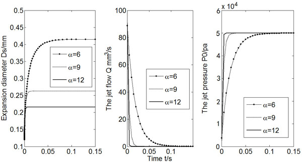
Fig. (5) shows calculated Ds, Q and Po vs. time for three different shear modulus (μ) values. A bigger shear modulus makes the expansion diameter smaller, and it takes less time for the flow rate to approach to zero.
Calculated Ds, Q and Po (µ = 1.1 × 10⁴, 2.7 × 10⁴, 4.5 × 10⁴).
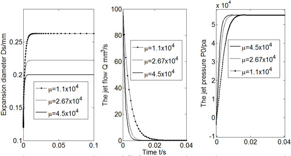
If the micro-needle array has a denser arrangement, that is, the total number of micro-needles increases, it takes longer time for Po to reach a constant value and for Q to drop to zero, as shown in Fig. (6). However, the change of micro-needle number does not alter the expansion diameter that the injection can achieve. In other words, the arrangement of the micro-needle array has little influence on the initial infusion effects.
Calculated Ds, Q and Po (N = 43, 100, 150).
Fig. (7) shows the results of Ds, Q and Po for the three different values of micro-needle diameter do, whereas other variables were kept unchanged. A larger do makes the expansion easier. As a result, the expansion diameter increases, and it takes longer time for the flow rate drops to zero. It is also found that the expansion diameter is about 2-3 times of the micro-needle diameter no matter what the micro-needle diameter is.
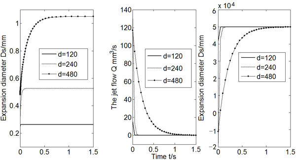
Calculated Ds, Q and Po (do = 120, 240, 480).
The calculation results of expansion model show that the expansion radius levels out instantaneously. The initial infusion of the micro-needle jet is largely restricted by the spherical expansion of the jet.
In calculation of the diffusion boundary, it is assumed that the diffusion is an independent process. The jet flow rate Q(t) from the above expansion calculation thus can be substituted into Equation (17) to obtain the diameter of the diffusion boundary Df (=2R). The physical properties of the human skin model used for the calculation of the diffusion boundary are listed in Table 2.
The physical properties used in the diffusion model calculation.
| Liquid absorption rate of blood vessel β (s-1) | Porosity ε | Liquid absorption rate of cells γ |
|---|---|---|
| 120 | 43 | 0.001 |
Fig. (8) shows both the diameter of diffusion boundary (Df) and the expansion diameter (Ds) varying with time from the beginning of the injection, using the flow rate Q(t) from the above expansion calculation with the system parameters listed in Table 1 and Table 2. As shown in Fig. (8), the diffusion boundary increases rapidly from the initial injection, and reaches a peak value in 0.09 to 0.1 seconds and tapers after that. The variation tendency of the diameter of the diffusion boundary is dependent on the jet flow rate, the liquid uptake rate of the cells, the blood vessels, and the space between tissues. At the beginning of the injection, Q(t) starts from a maximum value and then decreases rapidly. The diffusion boundary thus picks up rapidly from the beginning of the injection, reaching a maximum value soon before it decreases to close to the expansion boundary when Q(t) decreases to close to zero.
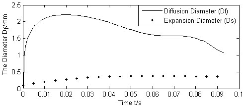
Calculated Df , Ds vs. injection time.
Since the resistance quickly accumulates during the expansion of the jets, and the flow rate quickly drops to zero for a typical piezoelectric micro-pump, the diffusion also stops quickly. Normally, the diffusion of the micro-needle jets is a relatively slow process. It is thus reasonable to assume that the diffusion process starts after the expansion process nearly stops and it will reach an equilibrium state while Q(t) /N is stable. The following calculation assumes that Q(t) /N remains constant from the point of expansion diameter reaching 0.4mm (injection time=0.9s), while other parameters of the properties in Table 2 varying.
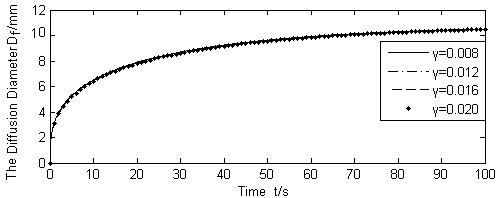
Calculated Df for different γ (Q(t)/N =1.667 × 10⁻⁹m3/s).
Fig. (9) shows the results of diffusion boundary diameter Df, for the three different values of liquid absorption rate of cells γ, whereas other variables were kept unchanged. Figs. (10, 11) show the calculation results of varying absorption rate of the blood vessel β, and the skin porosity ε, whereas other variables were kept constant as shown in Table 2, respectively.
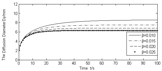
Calculated Df for different β (Q(t)/N =1.667 × 10⁻⁹m3/s).
It is seen from Figs. (9-11). that the diffusion boundary largely depends on the absorption rate of the blood vessel β and the skin porosity ε, and is relatively insensitive to the absorption rate of cells γ. Since γ is normally a magnitude smaller than, and both of them exist in the denominator of the exponential power in Equation (17), it is obvious that γ has little influence on the diffusion boundary. The absorption rate of blood vessel β has a reverse effect on size of the diffusion boundary. The increase of β will limit the permeability of the liquid, thus containing the diffusion boundary. On the contrary, the increase of skin porosity ε will increase the size of the diffusion boundary, thus increasing the permeability of the liquid.
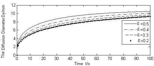
Calculated Df for different ε (Q(t)/N =1.667 × 10⁻⁹m3/s).
If Qmax(t) in Table 1 is fixed as a constant, the jet flow rate of Q(t)/N varies as the number of micro-needle varies, and its impact on the diffusion boundary is shown in Fig. (12). (Q(t) /N = Qmax(t)/N, Other parameters are listed in Table 1 and Table 2). The increase of jet flow rate of Q(t) /N will obviously increase the size of the diffusion boundary.
4. QUALITATIVE EXPERIMENTS
Since the infusion process of a micro-needle system is difficult to visualize, a single needle driven by a syringe pump was used for experimental study. The needle has inner diameter of 0.14mm and outer diameter of 0.32mm. The infusion syringe pump (Harvard Pump 11 Elite, Provided by InsTech Laboratories, PA, USA, infusion velocity from 1.28 pl/min. to 88.28 ml/min without load) has a microprocessor for actuation and is synchronized with a high speed digital imaging system (provided by Beijing Daheng Imavision, China, Transmission speed: 400Mbit/s, frame rate of 32 frames per second, exposure time 43 ~67s range, automatic shutter).
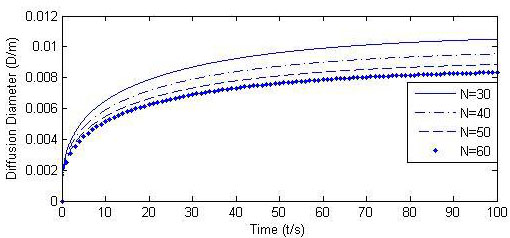
Calculated Df for different N.
Silicon rubber and polyacrylamide gel were chosen as model soft material for their skin like characteristics. Silicon Rubber is an incompressible, hyperelastic, isotropic, soft solid that is often used to replace human skin. It satisfies the Odgen model of strain energy that the current expansion model is based upon [18]. Polyacrylamide gel has the property of inelastic, absorptive, transparent, and is ideal for visualization. Overall, silicon rubber has the property close to SC and epidermis, and polyacrylamide gel is close to dermis and hypodermis.
In the experiments, liquid silicone rubber which contains A, B two materials (R-705A, R-705B, provided by Chengdu Zhonglan Chemical Engineering Research Institute, China), was mixed with ratio of 10:1, after centrifuged, then put into a drying oven for a period of time. The self made silicon rubber has Shore hardness of 10 HA. Polyacrylamide gel was created by adding initiators to acrylamide solution. 30% Acr/0.8% BisAcrylamide (SDS-PAGE, Provided by Nanjing KeyGen Biotech, China) was mixed with DI water to create acrylamide solutions. Gels were polymerized by the addition of 10% APS (45ml) and TEMED (12ml) to 6ml acrylamide solution, resulting 30% gel. The self-made polyacrylamide gel has Shore hardness of 8 HA.
Jet expansion in a silicon rubber through a single needle.
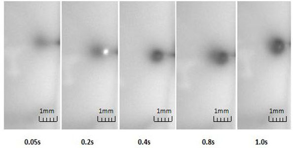
Fig. (13) shows the initial injection of the liquid in the prepared silicon rubber through the needle that was put approximately 2mm underneath the surface. The infusion velocity at the pump is set to be 50ml/min. The silicon rubber was placed under the aforementioned digital imaging system with the exposure time set to 50ms. It can be seen from the figure that the jet expansion quickly stops (within 1s of initial infusion) due to high resistance of surrounding material. The results agree with the analytic results from the expansion model.
Fig. (14) illustrates the initial injection of the liquid in the prepared polyacrylamide gel through the same needle and the same velocity setting of the pump. The figure is clearer due to more transparent feature of the polyacrylamide gel. The jet expansion is much bigger than that in silicon rubber, and keeps expanding after 1s. Polyacrylamide gel has the property of good absorption. Therefore, the expansion can be partly viewed as diffusion, and the results qualitatively agree with the analytic results from the dispersion model. In fact, the jet expansion becomes irregular in shape and disperses to particular areas after keeping injection for several seconds.
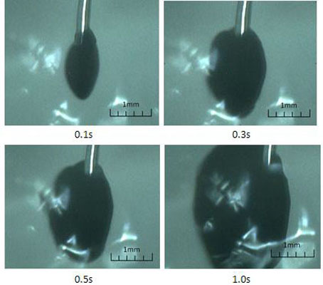
Jet dispersion in a polyacrylamide gel through a single needle.
5. DISCUSSION
Human skin is a composite material that consists of cells, tissues, nerves, blood vessels, and water. In general, the properties of stratum corneum and epidermis are closer to those of silicon rubber, and the properties of dermis and hypodermis are closer to those of polyacrylamide and water. The current model of micro-needle infusion may have guiding significances on practical micro-needle drug delivery depending on the location of transdermal injection.
Although micro-needle length will usually be greater than the thickness of the stratum corneum (SC) of the skin, the process of micro-needle puncture of the skin will cause deformation and tension of the stratum, result in changes of strain energy and hardness surrounding the micro-needle, and the actual depths of micro-needle insertion are below than expected [17], as shown in Fig. (15). The increase of strain hardening exponent and shear modulus from stratum and epidermis will make the liquid infusion more difficult, as indicated in Fig. (4). and Fig. (5). Many experimental studies show that the infusion through hollow micro-needles into the skin is limited by the resistance to flow caused by compressed dense dermal tissue [15, 16]. It also explains the reason that the commercialization of the micro-needle system driven by a micro-pump is difficult. If the micro-needles are just long enough to pierce through the layer of SC and epidermis without touching the nerves, the diffusion process may dominate and the infusion flow will be improved.
In reality, the dermis structure underneath the epidermis is a non homogeneous porous material that is difficult to be described by a few mechanical properties. The current model also assumes that the infusion expansion by each micro-needle in the array is an independent process. However, when the expansion grows to a certain level such that the expansion diameter or diffusion boundary is comparable to the distance of two neighboring micro-needles, the flow behavior will be affected, which makes the current assumption invalid. The current model describes the initial flow characteristics of the micro-needles infusion when the pump flow pressure is much higher than the capillary resistance pressure. In addition, since most of the liquid drug has low viscosity, it is reasonable to neglect the capillary resistance even the inner radius of the needles is very small.
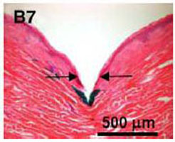
Deformation and tension of skin during insertion of micro-needles (the arrow indicating the site of needle penetration, photo courtesy of [17]).
CONCLUSION
An analytical model is presented to calculate the flow characteristics of the infusion of a micro-needle drug delivery system. It is assumed that the initial liquid infusion through micro-needles forms a spherical expansion and a spherical diffusion. During the expansion process, the skin is treated as a non porous, incompressible, hyper elastic, and isotropic solid. The calculations based on the current model lead to some interesting results: for a typical commercial piezoelectric micro pump, the flow expansion stops instantly and the flow rate quickly drops to zero, unless the pressure from the micro-pump is increased. It is assumed that the diffusion of the micro-needle jet is driven by the jet flow coming out of the micro-needle. The diffusion process is influenced by the absorption of the tissue cells, liquid carrying by blood vessels, and the solution filling the spaces between the tissues, while the diffusion through concentration gradient is neglected. The rapid drop of the jet flow rate resulted from the jet expansion process causes the diameter of the diffusion boundary increasing quickly at the beginning, then tapered off immediately after reaching a maximum value. If the jet flow rate remains constant, the diameter of the diffusion boundary increases with the increasing skin porosity, but decreases with the increasing absorption rate of the blood vessel, and is insensitive to the absorption rate of cells. The experimental results from the jet flow through a single needle in silicon rubber that fits into the assumption of the expansion model also show that the jet expansion as well as jet flow quickly stops after initial infusion. However, the phenomena of the jet flow in polyacrylamide gel show that the jet expansion is much larger and the jet flow will keep going as long as the pump pressure is enough. The polyacrylamide gel has good absorption property, and the results qualitatively agree with the analytic results from the diffusion model.
CONFLICT OF INTEREST
The authors confirm that this article content has no conflict of interest.
ACKNOWLEDGEMENTS
The current project is under support of China’s National Science Foundation (No. 51275142).
DISCLOSURE
Part of this article has been previously published in Biomedical Engineering and Informatics (BMEI), 4th International Conference 2011, (Volume:2), Pages: 913 - 917; DOI: 10.1109/BMEI.2011.6098420.