All published articles of this journal are available on ScienceDirect.
Numerical Simulation and Clinical Verification of the Minimally Invasive Repair of Pectus Excavatum
Abstract
Objective:
In this article we proposed a modeling method by building an assembled model to simulate the orthopedic process of minimally invasive surgery for pectus excavatum and got the clinical verification, which aims to provide some references for clinic diagnoses, treatment, and surgery planning.
Methods:
The anterior chest model of a 15-year-old patient was built based on his CT images; and his finite element model and the Nuss bar were created. Coupling of nodal displacement was used to connect bones with cartilages of the anterior chest. Turning the Nuss bar over is completed by rotating displacement of it. By comparing the numerical simulation outcomes with clinical surgery results, the numerical simulation results were verified
Results:
The orthopedic process of minimally invasive surgery of pectus excavatum was simulated by model construction and numerical analysis. The stress, displacement fields and distribution of the contact pressure between the Nuss bar and costal cartilages were analyzed. The relationship between correcting force and displacement was obtained. Compared with the of clinical results, the numerical simulation results were close to that of the actual clinical surgery in displacement field, and the final contact position of the Nuss bar and the costal cartilages.
Conclusion:
Compared with the rigid model, the assembled simulation model is in more conformity with the actual clinical practice. The larger curvature results in the maximum equivalent stress, which is the main reason for clinical pain. Soft tissues and muscles should be taken into account in the numerical simulation process.
1. INTRODUCTION
Pectus excavatum (PE) is the most common deformity of the chest wall. Nuss procedure is a novel minimal invasive surgical technique for the treatment of PE. The Nuss bar has changed the initial mechanical environment of the anterior chest, and has produced considerable stress which leads to postoperative pain [1]. Due to a lack of numerical simulation results, the planning and conducting of the Nuss procedure rely too much on the surgeons’ experience. In addition, it is difficult to consider the patient's individual differences. All these factors prevent the Nuss procedure from getting a high quality of treatment for PE.
With the numerical simulation of the Nuss procedure for PE, we can obtain the stress and strain fields of the anterior chest, correcting force and the distributions of contact pressure between the Nuss bar and the chest, and can provide the basis for conducting the orthopedic surgery and promote this transformation from surgeons’ experience to numerical simulation results in order to improve the surgical level of the Nuss procedure.
Numerical simulation of the orthopedic process of minimally invasive surgery for pectus excavatum involves three-dimensional (3D) reconstruction of the anterior chest, construction of the finite element models, connection of the bones and cartilages, and turnover of the Nuss bar, et al. J. D. Ye [2] has completed the 3D reconstruction of the anterior chest model, and imported it into the finite element analysis (FEA) software ANSYS (ANSYS Inc. USA) to construct the multi-body model and FEA model with assembly relationships of the anterior chest, which consists of about 198 964 tetrahedral elements, and applied a displacement to the sternum to get orthopedics. Y.B. Wei [3-4] and W.D. Wang [5] built 3D FEA model of the anterior chest without assembly relationships, which consists of about 649 433 tetrahedral elements and applied a displacement to the Nuss bar to raise the depressed sternum. But when the correction finished, the bar did not contact with the anterior chest wall. P.Y. Chang [6-7] constructed the FEA model of the anterior chest without spine, which consists of about 320 000 tetrahedral elements, and the displacement was also applied to the Nuss bar.
There are some main problems in the numerical simulation of PE. Firstly, although the modeling without assembly relationships is relatively easy, the connections between bones and cartilages are rigid, larger stiffness of connection will exaggerate the ability to resist deformation, which is not in conformity with the actual clinical practice. Secondly, as for the multi-body model with assembly relationships, inappropriate connection with bones and cartilages will cause the divergence of the numerical simulation calculation. Finally, existing technique cannot turn the Nuss bar over, which has significant differences in Nuss procedure and cannot estimate the contact pressure and its distribution between the thorax and the Nuss bar.
In this article, the 3D multi-body model and FEA model with assembly relationships of the anterior chest with PE are constructed, including the sternum, thoracic vertebras, ribs and costal cartilages, meanwhile, the 3D solid model and FEA model of the Nuss bar are created in ANSYS (ANSYS Inc. USA). Rotating displacement is applied to the Nuss bar so as to simulate the Nuss procedure. Since the Nuss bar contact with the sternum, ribs and costal cartilages in orthopedic process, nonlinear contact is considered in the numerical simulation. From the numerical simulation results, we have obtained the fields of displacement, stress and strain of the thorax and the Nuss bar, and have acquired the change of correcting force in the process of turning the Nuss bar over. The minimally invasive orthopedic surgery was designed according to the numerical simulation results, which has been verified by a Nuss procedure.
2. MATERIALS AND METHODOLOGY
2.1. 3D and FEA Model of the Anterior Chest
In this study, a 15-year-old patient with symmetrical PE was chosen for analysis, and spiral Computerized Tomography (CT) scan employed. The preoperative and postoperative spiral scans were made from the upper edge of the first thoracic rib to the lower edge of the 12th rib. 507 CT images with scanning interval of 0.8mm were obtained and saved in format of Digital Imagine and Communication in Medicine (DICOM). Then, the preoperative CT images were inputted into the medical image 3D reconstruction software Mimics10.1 (Materialise, Belgium) to establish the thorax 3D model of PE including the spine, sternum, thoracic vertebras, ribs and costal cartilages and so on. Then, it was imported to the FEA analysis software ANSYS (ANSYS Inc. USA) and assembled. Meanwhile, element types, material properties and mesh size were defined, 110 382 elements and 202 194 nodes were created. In ANSYS (ANSYS Inc. USA), the shape and position of the Nuss bar were designed according to clinical experience, and it was meshed into 600 elements and 3753 nodes. The total FEA model of the anterior chest and Nuss bar are showed in Fig. (1).
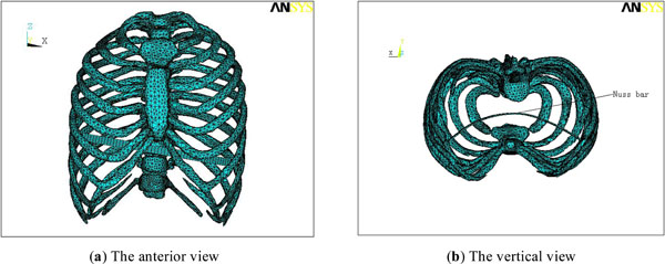
Total FEA model of the anterior chest and the Nuss bar Material properties.

The orthopedics schematic.
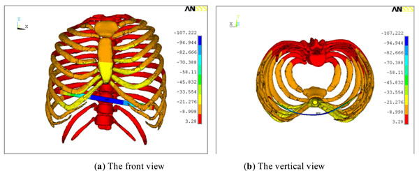
Y directional displacement field of the anterior chest and Nuss bar after correction (elevating direction).
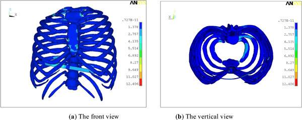
Von Mises stress field of the anterior chest and Nuss bar after correction.
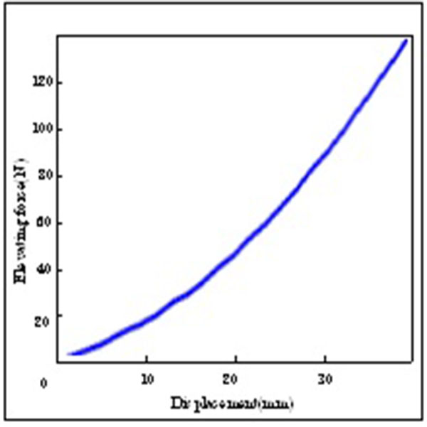
The curve of orthopedic displacement.
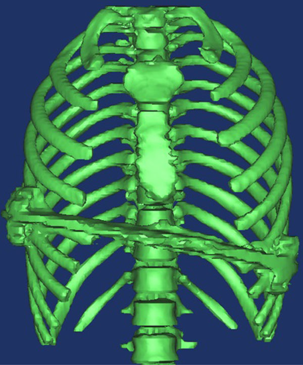
Postoperative thoracic 3D model of PE and elevating force.
The reference value of the material parameters
| Material Properties | Elastic Modulus(Pa) | Poisson Ratio |
|---|---|---|
| Cortical bone 1 | 1.0×10¹⁰ | 0.3 |
| Cortical bone 2 | 8.0×10⁹ | 0.3 |
| Spongy bone 1 | 1.0×10⁹ | 0.25 |
| Spongy bone 2 | 2.0×10⁸ | 0.25 |
| Costal cartilage 1 | 5.0×10⁷ | 0.3 |
| Costal cartilage 2 | 2.5×10⁷ | 0.3 |
The thoracic model includes bones and cartilages. The bones contained cortical bone and spongy bone. If the cortical bone and spongy bone were divided, a number of elements would increase sharply. As shown in Table 1, the equivalent elastic modulus of bones was calculated in accordance with the volume fraction of the cortical bone and spongy bone. In addition, the Nuss bar was made of titanium alloy, which has high strength and intensity, as well as good resistance to corrosion. Therefore, it is widely used as the substitute for the human body, such as bones, teeth, and hard tissue et al. The elastic modulus of titanium alloy is about 105 GPa, Poisson ratio is 0.3 The nonlinear contact was considered in the numerical simulation, the Solid186 element with intermediate node was selected.
2.2. Boundary Conditions and Constraints
Bones and costal cartilages of the 3D multi-body model of anterior chest were connected by the coupling of nodal displacement technique, which meant that identical displacements on adjacent nodes were defined between every adjacent vertebrae, between rib and vertebra, sternum and rib, costal cartilage and sternum. The connection of rib and vertebra included two couplings of nodal displacement: the one between rib and vertebra body, the other between rib and transverse process. At the same time, the 12 thoracic vertebrae were constrained.
Because the patient’s sunken position of PE was located at the costal cartilages of the xiphoid end, as well as the Nuss bar was tilted, it would successively contact with the posterior region of sternum and costal cartilages in the orthopedic process. The Gaussian integral point of the contact elements was chosen according to the contact test, and the normal penalty stiffness as well as penetration tolerance were determined by trial. Meanwhile, the augmented Lagrange multiplier method was used as the contact algorithm, the convergence criterion of residual force was adopted and its convergence accuracy was 0.1 %.
This turnover process of the Nuss bar was completed by applying rotary displacement function to simulate the orthopedic process of minimally invasive surgery.
2.3. The Orthopedics Schematic
A transverse incision about 2cm long was made at bilateral mid-axillary line horizontally. An artificial pneumothorax was established and thoracoscope was inserted into it. Under the guidance of thoracoscope, the Nuss bar with expanding surgical forceps was pulled in, and dragged across the posterior region of sternum with the convexity facing backward. After the Nuss bar reached the right position, it would be turned over. The sternum and anterior chest wall were elevated as expected. One end of the Nuss bar for support frame was set into the fixator, the other was sewed into the periosteum of rib, as shown in Fig. (2).
3. RESULTS
Fig. (3) shows that elevating displacement field of the anterior chest and the Nuss bar after it was rotated 180 degrees. The depressed sternum and costal cartilage had been elevated, and the deformity of PE was corrected. As the same time, the deformation of the sternum was more uniform than ribs, and the displacement values of the costal cartilages linked with the sternum was larger. In addition, both ends of the Nuss bar were just located at two ribs after correction.
Fig. (4) shows the Von Mises stress field of the anterior chest and the Nuss bar after correction. The maximum stress of the anterior chest was located in the joint of the second rib of the right chest and thoracic vertebra. Besides, the Von Mises stress located in the joints of the sternum and costal cartilages was also high.
According to the numerical simulation results, the spine had lateral displacement in the orthopedic process, but its value was smaller (only about 0.2mm). Therefore, the effect that orthopedic surgery had on scoliosis can be ignored because the PE was a symmetric. At the same time, the maximum Mises equivalent stress of spine was located in the second thoracic vertebra after the correction; the rest of stress was relatively small. The Nuss bar successively contacted with the sternum and costal cartilages in the orthopedic process of turning the Nuss bar over, the final position of the Nuss bar only contacted with the costal cartilages and the contact pressure was smaller in numerical value.
The numerical simulation results indicated the relationship between orthopedic displacement and elevating force in the sunken position. It is shown in Fig. (5).
The orthopedic surgery was conducted according to the numerical simulation results in the Military General Hospital of Beijing PLA. Fig. (6) shows the postoperative thoracic 3D model of the PE patient. Compared with clinical surgery results based on spiral CT, the simulation model was close to the postoperative outcome, and the final position of the Nuss bar only contacted with lesser costal cartilages. However, there were some differences in orthopedic displacement in the sunken position. The maximum displacement in the numerical simulation was 25mm, while 32mm in the clinical surgery. The orthopedic displacement of the sunken position in the clinical surgery was greater than the result of the numerical simulation when the tilted Nuss bar was lower than the sternum.
DISCCUSSION
By now, there are two kinds of model used to simulate the orthopedic process of minimally invasive surgery for PE: the entirety and the assembled model. The merits of the entirety model with no assembly relationship are relatively easy and consuming less time in establishment. With the rigid connection between bones, it will result in too large stiffness which may magnify the resistance to deformation of the rib cage, especially the resistance to deformation of the spines. Although the assembled model is more complicated and consuming more time in model establishment, it is in more conformity with the actual clinical practice. It will result in divergence in calculation if connected improperly.
The practices of numerical simulation indicated that the connection between bones had a significant effect on the calculated outcomes; especially the improper connection of the rib and transverse process segment would cause the divergence in numerical simulation process.
The numerical simulation also showed that the ribs would move forward and backward and a horizontal jitter would occur. The main reason was that the different contact areas of the Nuss bar and anterior chest had greater influence on the process of turning the tilted Nuss bar over.
The numerical simulation results showed that the maximum equivalent stress generated in orthopedic process was located in the joint of the first or second ribs and thoracic vertebra in neck, the reason for this phenomenon was that the curvature in the part of ribs was larger, which resulted in clinical pain.
The numerical simulation results also showed that the orthopedic displacement of the sunken location in the clinical surgery was greater than that of the numerical simulation when the position of the tilted Nuss bar was under the sternum, which resulted in obvious difference between clinical and numerical simulation results. In author’s opinion, the reason for error in numerical simulation is that soft tissues and muscles play an significant role on the ribs and costal cartilages in orthopedic process, because they are lifted by the Nuss bar in the clinical surgery while only soft tissues are taken into consideration in numerical simulation. Therefore, the effects of soft tissues and muscles should be considered in the numerical simulation process.
CONCLUSION
Although the simulation model with assembly relationship is complicated and consuming more time in creation, and is easy to result in divergence in calculation if connected improperly, it has been verified by clinical practice, and is in more conformity with the actual clinical practice, which means that assembled model improved the consistency with clinical practice and the reliability of numerical simulation. Since soft tissues and muscles played a certain role in orthopedic process on the ribs and costal cartilages, in order to improve the precision of numerical simulation process, soft tissues and muscles should be taken into account in reconstruction of the numerical simulation model.
CONFLICT OF INTEREST
The authors confirm that this article content has no conflicts of interest.
ACKNOWLEDGEMENTs
This work was supported by National Nature Science Foundation of China [11372221].

