All published articles of this journal are available on ScienceDirect.

Design and Development of a Prototype Electrotherapy Device
Abstract
This article describes a complete prototype system that can be used in electrotherapy treatments, that is, in medical treatments involving electric currents. The system is composed of two main blocks: the master and the slave. The Master block, whose main component is a CPU, controls the user interface. The Slave block, which is composed of a microcontroller and a wave generator, produces the appropriated voltages and currents compatible with the desired treatment. The whole system is powered by a 12 V power supply and the output signal voltage ranges between -100 V and 100 V. Despite the prototype being able of performing all the electrotherapy treatments in the low-medium frequency ranges, it was tested in aesthetic mesotherapy, namely in anticellulite, located anticellulite, antistretch, and antiflaccidity. In these treatments, the output signal is composed of an overlap of two frequencies: the first one is selected in the range of 1.2 kHz - 1.8 kHz and the second in the range of 0.07 Hz - 2 Hz. The system was tested in a clinical environment with real patients. It showed good results both in effectiveness of treatments and in terms of pain suffered by the patients.
INTRODUCTION
Electrotherapy is now commonly used in medicine. The process involves no pain and it is very effective in some diseases, so it has a wide range of applications [1, 2]. Cranial electrotherapy stimulation (CES) is a noninvasive procedure that has been used for decades to treat anxiety, depression, and insomnia in the general population [3, 4]. Additionally, in vivo studies were conducted to quantify the effectiveness of low-level direct electric current for the treatment of different types of tumors and certain types of cancer [5, 6].
The main method for pain management is medication. Another very different approach is the application of electric currents in the range of μA to mA, to specific areas of the head. While this may sound like a novel concept to most of us, years of research indicate that transcranial electrotherapy stimulation (TES) can work to noninvasively increase the release of endogenous opioids from pain management regions of the brain [7-9].
Recently, electrotherapy has been used in muscular pain treatment, [8], muscular spasms [9], infections, arthritis, hair loss, rheumatic diseases [10], anxiety control, acne, weight loss [11], stretch marks treatments [12], cellulite treatments, and skin rejuvenation [13, 14].
The protocols or treatments that this stimulator prototype is capable of generating embrace both low and medium frequencies of the electrotherapy spectrum [15]. The main groups of available treatments are shown in Table 1. When properly organized, the number of available treatments totalizes 26; 12 of which are programmable and 14 fixed. In programmable treatments, parameters like current, waveform or frequency can be altered by the operator over a wide range of values. For fixed protocols, current control is usually the only one necessary. Treatments are also different according to their electrical stimulus patterns and to the physiological effects they produce. Such effects can be extremely diverse for different configurations of a particular protocol [10].
Electrotherapy protocols [12]
| Protocol | Fixed/Programmable |
|---|---|
| Traebert | Fixed |
| Diadynamic | Fixed |
| Iontophoresis | Fixed |
| Galvanic | Fixed |
| Exponential | Fixed |
| Interferential | Fixed |
| Russian | Programmable |
| Faradic | Programmable |
| Healing | Programmable |
| Muscle | Programmable |
| Tanifying | Programmable |
| TENS* | Programmable |
Note: Classical and recently proposed treatments were combined. It is possible to obtain 26 different protocols as a whole.
* TENS: Transcutaneous Electrical Nerve Stimulation
This project was funded by a company, whose main goal was to develop a hardware prototype capable of performing aesthetic mesotherapy, reducing the technical expertise needed in treatment handling. On the other hand, since the prototype was designed to perform all low and medium frequency electrotherapy treatments, it is possible to expand its functionalities simply by upgrading software. Thus, despite the development of this prototype being targeted for aesthetic medicine, it can also achieve other types of treatments since the platform accepts other signals by changing only a few setup parameters.
Electronic devices applied to medicine must have precise accuracy and reliability factors. In particularly those in direct contact with the patient which leaves no room for error. In the past, all the options taken in the development of these devices were mainly related to the choice of materials and methods that used to maximize perfection, quality, reliability, and performance. In order to achieve the best results during a treatment, the equipment must guarantee clear and precise signal output with perfect repetition and very low error tolerance (below 1%).
As the main goal of the project was to develop a prototype to be used in aesthetic mesotherapy, we will focus our description in this area, despite the fact that the prototype can perform other electrotherapy treatments. In the aesthetic medicine area there are different types of treatments which can be seen as a resource of mesotherapy, namely:
- Anti-cellulite;
- Located anti-cellulite;
- Anti-stretch;
- Anti-flaccidity.
Each type of treatment needs a signal with single polarity, that is, the output current ranges between zero and a maximum value, selected by the operator. In all the treatments the applied signals obeyed to:
where V(t) is the output voltage, HF(t) is the high frequency waveform component, whose value ranges between 1.2 kHz and 1.8 kHz, and LF(t) is the low frequency waveform component, whose frequency ranges from 0.07 Hz to 2 Hz, that is, its period ranges between 0.5 and 14 seconds. Notice that V(t) must always be positive. If equation (1) gives a negative value, for a given t, the output is set to zero. Fig. (1) shows a waveform representation.
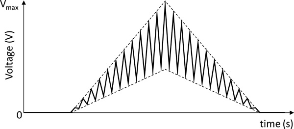
Desired output waveform of a mesotherapy treatment.
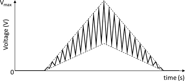
Output waveform of a mesotherapy treatment using negative-polarity drugs.

System architecture. The CPU operates as master and the microcontroller operates as a slave. The microcontroller functionalities are programmed by the CPU and then, the microcontroller can run alone.
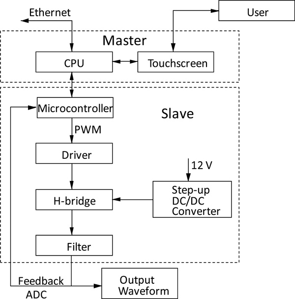
Block Diagram of the device internal structure and the links between the various sub-systems.
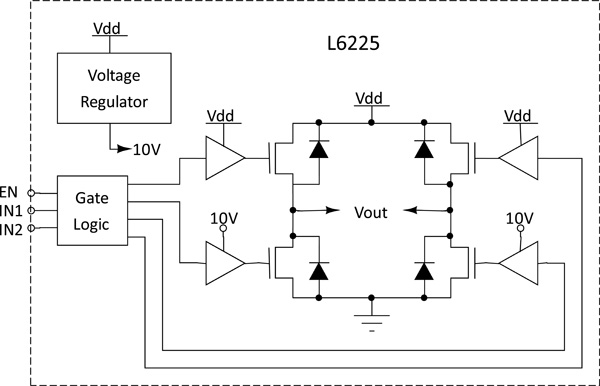
Driver circuit and H-Bridge circuit. They are based on BCD technology. Combines isolated DMOS Power Transistors with CMOS and bipolar circuits on the same chip.
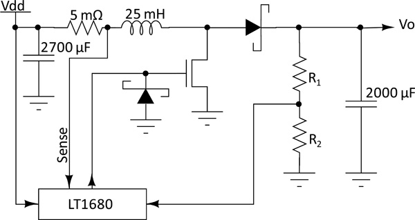
Step-Up circuit. High power, current mode switching power supply controller optimized for boost topologies. The IC drives an N-channel MOSFET, which switches the current in the inductor.
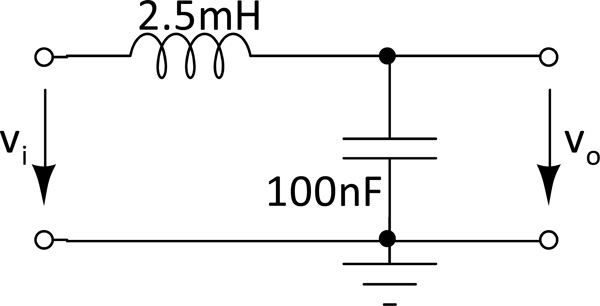
Second order low-pass filter with cut-off frequency of 10 kHz.
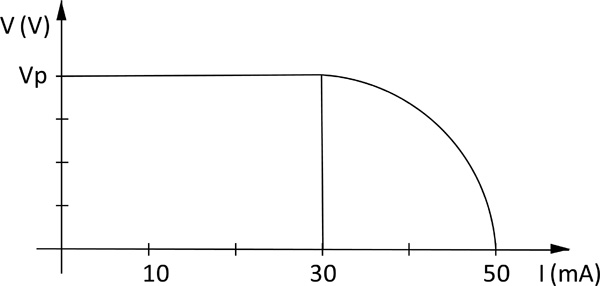
Output voltage versus current. For currents above 30mA the system protection responds by reducing the output voltage. Vp is the programmed output voltage.
Block diagram of the master algorithm.
Block diagram of the slave algorithm.
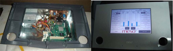
Prototype internal circuits and external appearance.
Signal obtained at the system output. It corresponds to the signal of Fig. (11) low-pass filtered, with 2 s in time axis and 5 V in voltage axis.
Ripple output signal.
Output waveform of the anticellulite program at 40% of full power.
Finally, the fact that some drugs only work with negative currents must also be considered. In this case, everything that was said in the preceding paragraphs is true, except that the current direction must be reversed for such drugs. This is done by ranging the voltage between a minimum negative value and zero. Fig. (2) shows the corresponding waveform.
METHODS
The main objective of this project is the development of a device prototype capable of performing electrotherapy treatments at low and medium frequency as referred above. In order to do so, the following characteristics must be taken into account:
- The programmable signal generator must be able of producing signals with frequencies up to 10 kHz.
- Due to practical issues, the system supply voltage cannot exceed 12 V, while the output signal may contain peaks that reach 100 V;
- The setup must have appropriate safeguards to avoid patient injuries;
- The user interface must be friendly, in order to be used by technical personal without expertise in electronics and computing;
- The setup must be flexible enough to allow for the introduction of new types of treatments without hardware upgrades;
- The setup must perform self diagnosis tests and report any type of anomaly;
- The setup must be able to work 24 h a day, 7 days a week.
The general system architecture proposed in this article is a master-slave structure since there are two control units: the high-level one (master) and a low-level one (slave).
The high-level control unit, central processing unit (CPU) or simply the master is responsible for supporting the user interface, exchanging and processing the necessary information between the user and the low-level control unit. The low-level control unit or slave is responsible for converting digital data, sent by the high-level control unit, to analog signals, which are directly applied to the patient. Its main component is a microcontroller. The low-level control unit, once programmed with a treatment data, can operate alone. Nevertheless, it may be useful to maintain the high-level control unit connected for debugging, treatment monitoring and error or malfunction detection. Fig. (3) shows the system architecture.
The Master block is composed of a processor unit, a touch screen and an Ethernet interface, while the Slave block is made up of a microcontroller, a driver, a step-up DC - DC converter, a H-bridge, a filter and the patient’s protection circuit. Both master and slave blocks communicate between themselves by means of a USB interface. Fig. (4) shows the block diagram of the whole system.
The CPU is the head of the system. It is responsible for gathering all the data that comes from the user interface console, processing it and calculating the appropriated coefficient vectors that will be used by the microcontroller to produce the corresponding output signal.
If we consider that the technical personal do not have expertise in computing and electronic technologies, it is important to provide an intuitive graphical interface. For this purpose, a touch-screen monitor was used to operate the device. The programming language used was C++, associated to an Open GL platform in order to satisfy several requirements, namely the real time operation, the support for microcontroller systems and achieving the system’s maximum graphic potential. The software was designed for a set of specific treatments where the operator does not need to change the characteristics of the electrical signals, except for the maximum amplitude that can change from patient to patient. Nevertheless, it allows for new signals to be programmed by a specialized technician. It is important to point out that this platform is based on a Linux operating system; due to its great potential for real time operation associated with the advantage that it being free software, making it easier and cheaper to commercialize the system.
Another particular feature is the system’s versatility, which allows firmware upgrades and interconnection with other devices by the Ethernet interface, in order to allow a huge range of treatments.
The interface between master and slave units is achieved by means of a USB connection due to its large bandwidth and plug-and-play interoperability. A full-duplex low speed (1.5 Mbit/s) data rate connection is used, which guarantees up to 512 kbit/s of bandwidth in each direction. The Bus topology used is the Reduced Host Topology which has a unique USB port and does not handle full USB tree with hub. This means that a reduced host controller is designed to handle a unique point-to-point connection with a unique USB device.
All interconnections between CPU and other functional blocks are bidirectional, allowing a continuous feedback that enables instantaneous detection of any anomaly.
The low level control unit main block is a microcontroller which is responsible for assembling the information sent by the CPU, in order to drive the H-Bridge. It calculates the PWM (Pulse Width Modulation) ON / OFF times, generating the desired signal to the system output. In order to generate signals with frequencies up to 10 kHz, the sampling frequency used in the microcontroller is about 50 times higher than the output signal frequency to ensure a low ripple at the filter output. In order to achieve that, an 8 MHz crystal was used. The microcontroller was the AT90USB1287, which is a low-power CMOS 8-bit unit, based on AVR with 64/128K bytes of ISP Flash, a USB device controller with full speed and low speed data transfer support and an enhanced RISC architecture. By executing powerful instructions in a single clock cycle, the AT90USB1287 achieves throughputs approaching 1 MIPS per MHz allowing the system designer to optimize power consumption versus processing speed.
The microcontroller output signal produces a peak voltage of 3.3V. To manage an effective treatment it is necessary to amplify this signal to higher levels, which can reach 100 V, depending on the treatment. To carry out this task, an H-bridge with two quadrants was implemented, allowing the change of the signal output polarity according to the corresponding treatment. The H-Bridge was implemented by means of the STMicroelectronics chip L6225, which is a DMOS Dual Full Bridge device that combines isolated DMOS Power Transistors with CMOS and bipolar circuits on the same chip. Fig. (5) shows the schematic diagram of the driver and the H-bridge.
Standard requirements imposed on medical equipment do not allow power systems, responsible for generating treatment signals, to have input voltages higher than 12 V. Nevertheless, to obtain the expected results, the signal output must produce peaks up to 100 V. This is achieved by means of a step-up DC to DC converter circuit, which provides up to 100 V with small ripple and 500 mA of maximum output current. In this application, the current will not exceed 50 mA. The step-up DC to DC converter circuit is implemented with the Linear Technology LT1680 device. The schematic diagram of the converter is shown in Fig. (6).
The filter block of Fig. (4) is responsible for the decrease of the ripple generated by the PWM to accepted levels. It is a second order low-pass LC filter, with a cut-off frequency of 10 kHz. Fig. (7) shows the schematic diagram of the filter. Its transfer function is given by:
where , and R is the resistance of the coil. The cut-off frequency of 10 kHz can be achieved by making L = 2.5 mH and C = 100 nF.
All equipment must comply to safety rules imposed by responsible entities. Therefore, in addition to the main objective, that is, the electrotherapy equipment, we must also ensure the safety of the patient. In so doing, a current limiter was introduced in the signal output. When the current reaches values above 30 mA, the output voltage of the circuit is lowered. Fig. (8) shows the output voltage waveform as a function of the current. This current limitation is implemented by the microcontroller through the feedback loop, that is, the output voltage is feed back to the microcontroller by means of an ADC (analog to digital converter). This feedback loop also allows the monitoring of the output voltage, error checking and malfunction detection.
Fig. (9) shows the block diagram of the master software algorithm. The master operation starts by waiting for the user instructions. After that, it processes the user instructions and sends the appropriate commands to the slave. The program then enters a loop controlled by a timer. Inside this loop the master only overlooks the slave activity. When the treatment time is achieved or in an error condition, the program leaves the loop, it sends a switch-off order to the slave, and waits for new user instructions.
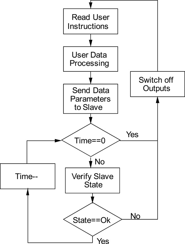
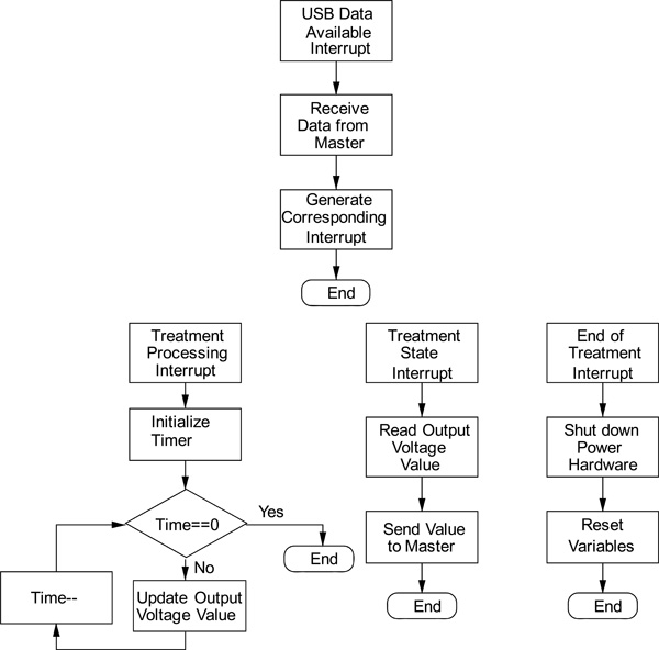
Fig. (10) shows the block diagram of the slave software algorithm. It consists of four independent subroutines, each one activated by an interrupt state.
The first subroutine is activated when data is available at the USB port. In this case, the microcontroller reads the data, processes it and generates an appropriate interrupt condition in order to activate one of the other three subroutines. The appropriate interrupt conditions are: treatment processing, treatment state and end of treatment.
The second subroutine is activated by the treatment processing interrupt. It starts by initializing the timer. Then, it enters a loop controlled by the same timer. Inside the loop, the output voltage is updated by reprogramming the PWM controller.
The third subroutine is activated by the treatment state interrupt. This interrupt is activated by two events: by the master, asking for feedback; and in a timer-controlled event, that implements the protection feedback loop described above. When this subroutine is activated, it only reads the output voltage value and sends it to the master.
The fourth subroutine is activated by the end of treatment interrupt. When this interrupt is activated, the microcontroller switches-off all the power devices and resets all the internal variables.
Fig. (11) shows two pictures of the prototype.
EXPERIMENTAL PROCEDURE AND RESULTS
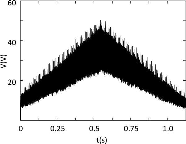
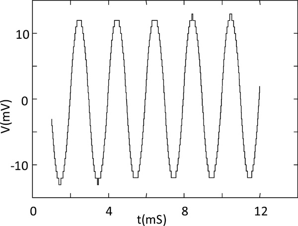
The signal output is a sum of two components: a low frequency of 0.07 Hz (Period = 14 s) and a high frequency of 1.8 kHz. The filter eliminates the high frequency components, produced by the PWM modulator, and all signal variations are smoothed. Fig. (12) shows the system output waveform and Fig. (13) shows a detail of the waveform of Fig. (12) for only 5 periods of the PWM wave, that is, for 10 μs. In this figure, it is possible to observe that the ripple has 11 mV of amplitude and do not influence the treatments.
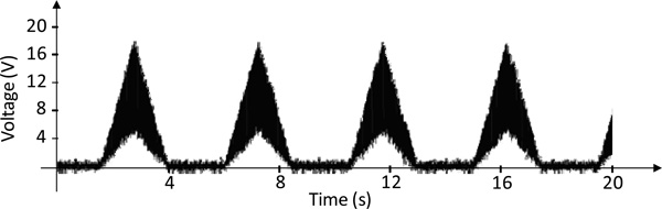
Fig. (14) shows the output waveform of the anti-cellulite program at 40% of full power.
Another aspect that was tested with real patients is the risk of skin burn. The tests showed that the greater risk occurs in the electrode that acts as anode. Nonetheless, the risk is substantially decreased if some of the following rules are applied:
- The electrodes must be very carefully applied to the skin, in order to avoid hot spots,
- Electrodes must be frequently and deeply moistened in order to increase electrical and thermal conductivity,
- The DC current must be switched on with a slow increase of intensity.
When these rules are followed, the patients feel a very reduced pricking or nothing at all.
The prototype was tested in a clinical environment, with real patients. The results of these tests are subjective and consist of the opinion of the technicians and patients. When asked about the effectiveness of the treatment, their answers were mainly “good” and “very good”. When asked about filling pain, the answers were “no pain” and “a little pricking”.
CONCLUSIONS
This article described a complete system prototype for use in low and medium frequency electrotherapy. The system is composed of a master-slave architecture in which the master block is based on a CPU and the slave block is based on a microcontroller. The first system prototype dedicated to the aesthetic mesotherapy, has already been manufactured and tested in laboratory conditions with performances that have corresponded to those expected.. It was also tested in a clinical environment, with real patients. The results of these tests are more or less subjective since they consist of the opinion of the technicians and patients, but almost every one considered the performance of the prototype as good or very good.
ACKNOWLEDGEMENTS
Acknowledgement of funding
CONFLICTS OF INTEREST
Any conflicts of interest.