All published articles of this journal are available on ScienceDirect.

The Development of a Myoelectric Training Tool for Above-Elbow Amputees
Abstract
The objective of above-elbow myoelectric prostheses is to reestablish the functionality of missing limbs and increase the quality of life of amputees. By using electromyography (EMG) electrodes attached to the surface of the skin, amputees are able to control motors in myoelectric prostheses by voluntarily contracting the muscles of their residual limb. This work describes the development of an inexpensive myoelectric training tool (MTT) designed to help upper limb amputees learn how to use myoelectric technology in advance of receiving their actual myoelectric prosthesis. The training tool consists of a physical and simulated robotic arm, signal acquisition hardware, controller software, and a graphical user interface. The MTT improves over earlier training systems by allowing a targeted muscle reinnervation (TMR) patient to control up to two degrees of freedom simultaneously. The training tool has also been designed to function as a research prototype for novel myoelectric controllers. A preliminary experiment was performed in order to evaluate the effectiveness of the MTT as a learning tool and to identify any issues with the system. Five able-bodied participants performed a motor-learning task using the EMG controlled robotic arm with the goal of moving five balls from one box to another as quickly as possible. The results indicate that the subjects improved their skill in myoelectric control over the course of the trials. A usability survey was administered to the subjects after their trials. Results from the survey showed that the shoulder degree of freedom was the most difficult to control.
1. INTRODUCTION
Myoelectric prostheses are robotic prostheses that are controlled via electromyography (EMG) electrodes attached to the residual muscles of amputee patients. The patient is able to control the velocity of the prosthesis actuators by voluntarily contracting their residual muscles. The objective of myoelectric prostheses is to restore some functionality to the patient and by doing so help improve their quality of life.
Part of the difficulty in learning to use myoelectric prostheses comes from how they are normally controlled. The conventional control methods currently employed in myoelectric prostheses map an estimate of the signal strength from a single surface EMG signal measured off of a single muscle group to the velocity of a single actuator on the robotic prostheses. The patient is required to modulate their signal above a threshold value after which the velocity of the actuator can be controlled in an on/off or proportional manner. For example an above elbow patient could use their biceps to control hand opening and their triceps to control hand closing. In the literature this type of controller is known as a two-state amplitude modulation controller [1]. Since the patient is limited by the number of muscle sites available and higher level amputees have less muscle sites only a limited number of degrees of freedom (DoF) on an actuator can be controlled at a time. To circumvent this problem, switches are added to the control scheme that can allow a patient to cycle through available functions sequentially. These switches can be controlled by an additional EMG channel or a linear displacement transducer. Unfortunately, these control methods are somewhat unintuitive since they require the patients to modulate muscles individually and sequentially instead of groups of muscles simultaneously. More advan-ced myoelectric controllers in development use combined muscle signals via pattern-recognition techniques to control the movement of the robotic prostheses [2-4]. It appears that these pattern recognition methods are not yet available in commercial myoelectric prostheses.
A surgical development called targeted muscle reinnervation (TMR) reinnervates residual nerves into healthy muscle tissue and creates more muscle sites that can be used for control purposes [5]. Without this surgery above-elbow amputees are typically limited to controlling one DoF sequentially using two or three muscle sites. After the TMR surgery the patients can get as many as five muscles sites, which can potentially allow them to control two DoF simultaneously while still having one muscle site available for switching. The Glenrose Rehabilitation Hospital (GRH) in Edmonton, Alberta, Canada has recently started performing these surgeries and needs a myoelectric training system with increased functionality in order to accommodate the TMR patients. Through discussion with prosthetists at the GRH it was revealed that the current method of training TMR patients involves having them imagine moving their phantom limb and leaves much room for improvement.
In consultation with the GRH and the MTT design team the objectives and scope of the project were defined. The first objective of the MTT is to help upper limb amputees (both TMR and non-TMR) learn to use myoelectric technology in advance of receiving their actual myoelectric prostheses. Within this objective the MTT will also be useful as an evaluation tool to determine whether a myoelectric prostheses will be a good fit for a patient in advance of them starting the wheels going on the funding process. The second objective is for the MTT to be used as a research platform for testing new pattern-recognition controllers. This objective will be tackled in collaboration with the Reinforcement Learning and Artificial Intelligence group (RLAI) from the Computing Science (CS) department at the UofA. The scope of the project will include the design, manufacturing and testing of an initial proof of concept MTT prototype, which meets the core requirements outlined in the following subsections.
1.1. SENIAM Guidelines
The SENIAM (Surface EMG for a Non-invasive Assessment of Muscles) guidelines were released in 1999, with the aim of trying to standardize EMG measurement methodologies across research groups [6]. The SENIAM guidelines make recommendations pertaining to the design of EMG electrodes, their positioning, and EMG signal processing and acquisition. The relevant parameters were extracted from the SENIAM guidelines and used as design requirements for the electrical subsystems of the MTT.
1.2. Review of Training Systems
A review of existing training systems in the literature and commercial industries [7] was utilized in order to determine the strength and weaknesses of current systems and areas for improvement that could be included in the MTT. In terms of significance, training in general was found to be an important factor in successful fittings of children [8-10]. However, for adults training was not found to have a significant impact on acceptance rates [11, 12]. There is currently a gap in the literature between showing that a patient is able to learn with a training system and showing that training actually helps improve their clinical outcome. Future clinical studies that focus specifically on training systems need to be performed in order to determine whether these devices can be linked to improved clinical outcomes.
The training systems in the literature included the following types of devices: signal strength displays [13], myoelectrically controlled video games [14-17], robotic arms [18], and computer simulations [19-24]. The devices in the literature were found to have an emphasis on being platforms for researching new myoelectric control methods rather than a training focus on helping patients learn to use the conventional control schemes commonly used in commercial prostheses. The systems with a training focus were typically limited to controlling only a single degree of freedom on a myoelectric hand (i.e. hand open/close) using two EMG electrodes.
The training systems available commercially included signal display devices [25, 26], and Otto Bock’s Myoboy [27]. The MyoBoy included functionality for signal display, a simple video game, and a myoelectrically controlled hand available as both a 2D simulator and an actual physical robotic hand. The application focus for these commercial systems was found to be exclusively training to use each company’s myoelectric prostheses and all devices were limited to controlling a single degree of freedom using two EMG electrodes.
From the review of myoelectric training systems several key requirements and improvements have been identified. Future training systems should be affordable, portable, and reliable with features to evaluate and record patient performance that can be used at a rehabilitation center or remotely by the patient. The systems should also be designed so that they are adaptable to conventional and state of the art control schemes. They should be modular to accommodate patients at different amputation levels including TMR and non-TMR patients. In order to ensure that patients have motivation for practice the devices should be fun and ergonomic. Multiple training methods should be included as options such as signal strength display and EMG control of simulators, robotic arms, and video games.
1.3. Design Specifications
A design specification matrix was compiled using all of the information gathered from the initial research. The requirements were broken up into the following subsystems: mechanical, electrical, and software. Some of the key requirements are given below. The overall system cost was specified to be CAN $6000.
In the mechanical section the key specifications were for the robotic arm, which needed to be approximately half scale, anatomically correct, and weigh about five to ten pounds. The robotic arm should include five DoF which mimic the DoF of below and above elbow prostheses available on the market. The target cost for the robotic arm was CAN $1000.
The electrical subsystem included requirements for the robotic arm actuators and the EMG acquisition hardware. In order to mimic commercial prostheses the actuators needed to be velocity controlled and to include positional feedback for implementation in safety features. Five EMG electrodes and a data acquisition (DAQ) system with at least five differential analog input channels were specified by the GRH. A decision was made to specify that the electrodes should run off of DC battery power on this prototype in order to minimize the risk associated with improper patient isolation. Future clinical prototypes that follow the ISO and IEC standards may not have this requirement and instead use medical grade power supplies and AC power. The target cost of the electrical subsystems was CAN $5000.
In the software subsystem specific requirements related to processing the acquired EMG signal, controlling the robotic arm, and displaying all of the necessary information to the patient via a graphical user interface (GUI). The desired conventional control scheme was specified by the GRH with a delay time of 0.200 seconds or less. The core features for the GUI were also specified and having a 3D simulator was noted as a desirable feature. The software development environment for the EMG controller was chosen at the outset of the project to be MATLAB’s xPC Target real-time prototyping environment. This development environment was chosen because of the compatible hardware already available to the author at no cost as well as previous design experience from other projects. The environment includes pre-made plug and play driver blocks for many DAQ cards and a signal processing toolbox that can be used to save development time on low level software and EMG signal analysis respectively. Using a real-time environment also helps avoid some of the delays and complexities associated with threading on non real-time computers.
2. METHODS
The design of the MTT research prototype and the experimental methods used to evaluate its performance are described in this section. The overall system flow diagram can be seen in Fig. (1). When possible the least expensive components still meeting the design requirements were chosen in order to reduce the system costs. The overall cost of the MTT prototype was CAN $5400 coming in slightly below the target cost of CAN $6000. The next few subsections describe the components selected and development work for each subsystem in detail.
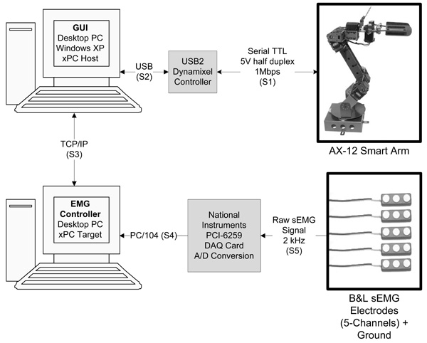
System flow diagram of the MTT research prototype.
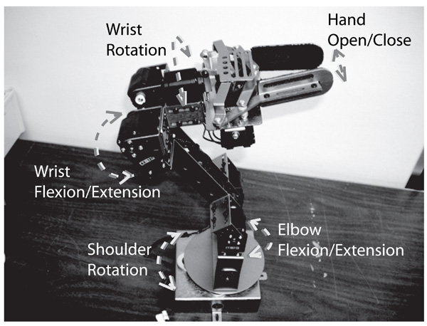
Crustcrawler’s AX-12 Smart Arm and its available degrees of freedom including: shoulder rotation, elbow flex- ion/extension, wrist flexion/extension, wrist rotation, and hand open/close.
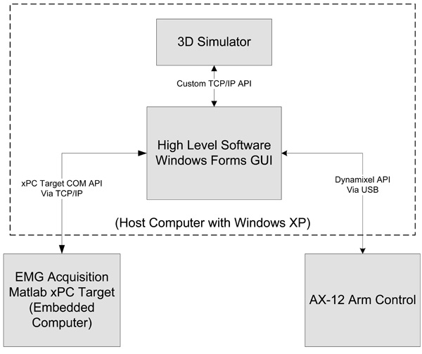
A block diagram showing the overall software architecture of the MTT.
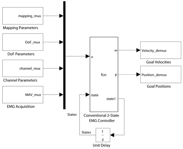
The top level block diagram of the EMG Acquisition and Control Software.
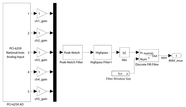
A block diagram of the EMG acquisition subsystem.
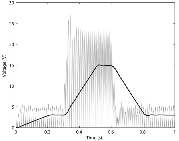
Signal Amplitude versus Time (seconds) of a simulated EMG signal. The grey signal (thin line weight) is the rectified signal and the black signal (heavy line weight) is the mean absolute value.
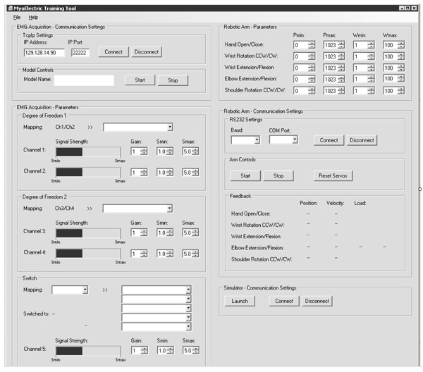
A screenshot of the MTT GUI.
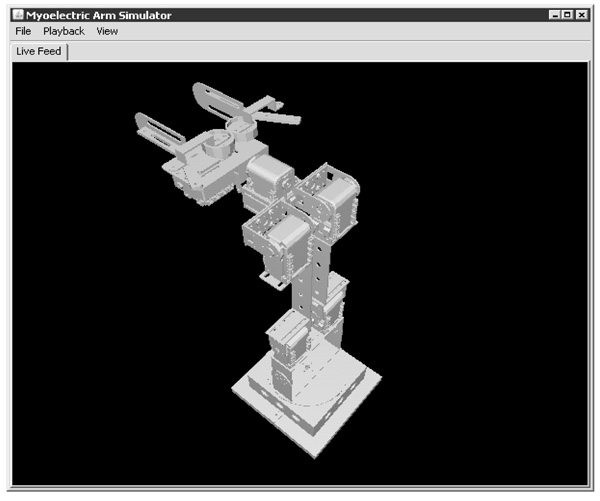
A screenshot of the MTT Simulator.
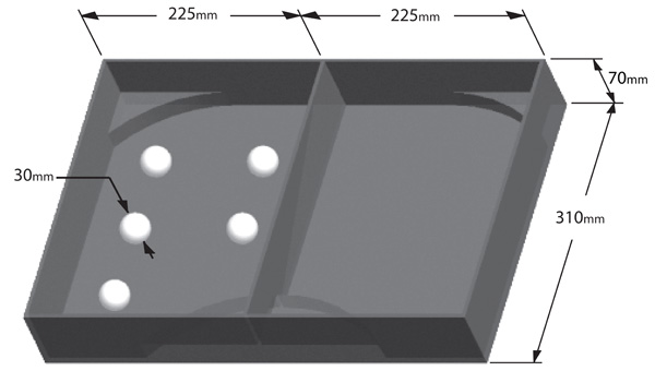
Illustration of the experimental setup including boxes and balls.
The averaged trial times for when the subjects performed the task using their actual left arm. The error bars represent ± 1 standard deviation.
The averaged trial times for when the subjects performed the task using the EMG controlled robotic arm. The error bars represent ± 1 standard deviation.
The controller evaluation results from the usability survey. The error bars represent the standard error in the mean. Note that 5 is the best rating and 0 is the worst rating.
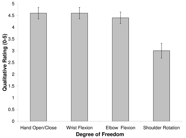
The DoF evaluation results from the usability survey. The error bars represent the standard error in the mean. Note that a rating of 5 corresponds to a DoF that is easy to control and 0 corresponds to a DoF that is very difficult to control.
2.1. Mechanical Subsystems
The main mechanical components are the links and joints of the robotic arm. The AX-12 Smart Arm kit, developed by Arizonan robotics company Crustcrawler, was selected as the robotic arm for the MTT. Fig. (2) illustrates the AX-12 Smart Arm and its available degrees of freedom including: shoulder rotation, elbow flexion/extension, wrist flexion/extension, wrist rotation, and hand open/close. The AX-12 Smart Arm meets all of the desired specifications except some of the relative link proportions are not quite anatomical. The robotic arm is secured to a table using adjustable clamps.
2.2. Electrical Subsystems
The actuators used in the AX-12 Smart Arm are the AX-12 Dynamixel servomotors. Seven motors provide the required degrees of freedom with the flexion/extension DoFs using two servos because they are the most heavily loaded. Each servo has positional or velocity control along with positional, velocity, temperature, and load feedback. In the event of the temperature or load becoming too high the servos will automatically shut down providing a valuable safety feature. The positional restraints can be set within the internal servo controller in order to prevent the arm from swinging back towards the patient. The actuators are daisy chained together and controlled by the target embedded computer via the USB2Dynamixel controller through a USB interface. Power is supplied to the AX-12 servos via an off-the-shelf power harness and power supply kit.
The BL-AE-N surface EMG electrodes developed by Californian company B+L engineering were selected for the MTT and closely follow the SENIAM guidelines. The stainless steel electrodes are arranged in a single differential configuration and include a built in pre-amplifier with a gain of about 330 that helps scale the acquired EMG signal close to the desired ±5V range of the DAQ system. The electrodes have a common mode rejection ratio (CMRR) of 95dB that helps reduce noise in the acquired signals. The input impedance is greater than 100Mohms and helps to prevent current from leaking back into the patient in fault conditions. The bandwidth of the electrodes is 12 to 3000Hz with a 3dB roll off. The EMG electrodes are powered by two 9V DC batteries via a custom powering harness and are secured to the residual limb of the patient using wrist bands or velcro straps.
The EMG signals are sampled at 2kHz by a National Instrument (NI) PCI-6259 DAQ card with 16-bit resolution. The EMG electrodes connect directly to a shielded NI SCB-68 connector block, which pass the signals onto the PCI-6259 via an off-the-shelf cable. The PCI-6259 is connected to the target computer via a PCI slot and the target computer is connected to the host computer via a TCP/IP connection and standard ethernet cable. The target and host computers are standard desktop computers running on the dedicated xPC Target kernel and Windows XP operating systems respectively.
2.3. Software Subsystems
The overall software architecture can be seen in Fig. (3). The software was broken down into the following subsystems: EMG Acquisition and Control, GUI, Robotic Arm Control, and the MTT simulator. Whenever possible, software subsystems were connected to each other through existing application programming interfaces (API) in order to save on development time. The EMG Acquisition and Control subsystem connects to the GUI via the xPC target COM API available in MATLAB and the Robotic Arm Control subsystem connects to the GUI via an existing Dynamixel API developed by Agave Robotics [28]. The simulator connects to the GUI via a custom API created by the MTT simulator design team.
2.3.1. EMG Acquisition and Control
The EMG Acquisition and Control software was created in the MATLAB R2009b simulink environment using the xPC target and signal processing toolboxes. An overview block diagram of the software can be seen in Fig. (4). The timestep of the software is 0.0005 seconds, which corresponds to the 2kHz sampling rate of the DAQ card. The software is compiled using the Visual C++ compiler from Visual Studio 2008 and can be loaded directly onto the target computer using the xPC Target embedded option. Within the xPC Target environment the software runs under hard real-time conditions, which means that if all the required operations cannot be completed within this timestep then the software will not execute at runtime. The software was also designed to be modular so that different conventional or pattern recognition controllers could be easily swapped in or out.
A graphical representation of the EMG acquisition subsystem can be seen in Fig. (5). The PCI-6259 driver block outputs the raw EMG signals for each channel. The signals are amplified by a digital gain, which can be controlled by the patient or therapist through the GUI. A notch filter at 60Hz removes power line noise and a high pass filter with a cutoff frequency of 10Hz removes motion artifacts. The next step is to estimate the signal strength by extracting the mean absolute value (MAV) as described in [1]. In order to do this the signal is rectified and averaged using a moving average filter that uses 400 points. This corresponds to a 0.200 second delay between when a patient initiates a contraction and when the level stabilizes at the increased amount. This delay effect is illustrated from simulation results in Fig. (6). The trade-off is that decreasing the delay causes the output signal to become less smooth. A 0.200 delay was used in order to get the maximum smoothness of the MAV within the constraints of the design requirements.
The conventional 2-state EMG controller was designed as per the GRH’s requirements in order to mimic controllers available on commercial prostheses. The controller uses four EMG channels measured from four separate muscle sites to control up to two DoF simultaneously on the robotic arm. Each degree of freedom is controlled by an antagonistic pair of muscles on the forearm or upper arm. When possible control schemes are setup so that the mappings are as intuitive as possible for the patient. For example the biceps and triceps could control the elbow flexion and extension DoF on the robotic arm. A fifth channel is also available in order to switch sequentially through a list of DoF on one of the channel pairs. The mapping, DoF, and channel parameters are specified in the GUI and allow the therapist to customize the control scheme for each patient. The mapping parameters specify which DoF on the robotic arm that the EMG channel pairs are mapped to as well as the switching list if enabled. The DoF parameters specify the minimum and maximum angular velocities and the positional constraints for each DoF on the robotic arm. The channel parameters specify the maximum and minimum signal thresholds. When the MAV is below the minimum signal threshold the robotic arm does not move and holds its position. Above the maximum signal threshold the angular velocity is held constant at the maximum allowed amount. Since a given DoF can only move in one direction at a time a “first past the post algorithm” was created in order to give preference to the movement corresponding to the channel that first reaches its minimum signal threshold. The outputs from the controller include the desired angular velocities and directions of rotation for each servo for each timestep. It should be noted that the paired servos for elbow and wrist flexion face away from each other and need to be rotated in the opposite directions.
2.3.2. Graphical User Interface
The GUI of the MTT software subsystems can be seen in Fig. (7). The GUI was designed in Microsoft Visual Studio 2008 using Microsoft Visual Basic (VB) and the Microsoft .NET 2.0 framework. VB was chosen as the programming language since it is supported by all of the existing and custom APIs. The GUI allows the user to specify communication settings for connecting to the xPC Target computer, robotic arm, and simulator. The EMG control parameters can be adjusted and saved in order to tailor the controller to each patient. Feedback in the form of the MAV for each EMG channel and the angular position, velocity, and load of each DoF are available. Through the file menu the user is able to save or open profile files that record all of the GUI settings.
2.3.3. Robotic Arm Control
Behind the scenes the GUI works by sampling the desired angular velocities and rotation directions from the target computer every 30 ms via the xPC Target COM API and then passing the signals onto the Dynamixel bus using the Dynamixel API. The AX-12 servos are controlled using a serial communication protocol that operates at 1Mbps on a half duplex multi-drop serial bus. Commands can be sent to each servo one at a time or in some cases broadcast to all the servos at once in a single packet. In order to save on the amount of messages that need to be sent in this application the broadcast method was used to send the velocity and position commands to the servos. For querying feedback from the servos the individual command method had to be used.
2.3.4. Simulator
The simulator features included a 3D visual representation of the robotic arm, recording and playback options, a modular structure in order to allow for future improvement, and an API for interfacing with the GUI. The current version of the simulator is limited to biofeedback tasks and is implemented via a kinematic model with rigid and massless links. The first objective of the simulator was to provide a training option for patients in situations where using the actual physical robotic arm are infeasible. The second objective of the simulator was to be used for evaluating new experimental myoelectric controllers as an intermediate step before trying them on the physical robotic arm. The 3D CAD model of the AX-12 Smart Arm was created in PROE Wildfire 4.0. The simulator was designed in the java environment and is platform independent. An illustration of the simulator can be seen in Fig. (8).
2.4. Experimental Methods
Experimental trials were performed by five able-bodied subjects using the MTT to perform a basic motor-learning task. Study objectives were to show that people could learn to use the MTT using a standard training program and to gain qualitative insight into the strength and weaknesses of the system in order to identify areas for future improvement. The study was approved by the Health Research Ethics Board (HREB) of the UofA and the subjects participated as volunteers with informed consent.
The task selected for this study was a modified version of the standard box and blocks task [29]. Modifications were necessary in order to adapt the size and shape of the boxes to the fixed elbow joint and limited workspace of the robotic arm. In addition, instead of moving as many blocks from one box to another in 60 seconds, the subjects in this study were required to move five balls from one box to another as fast they could with the performance indicator being the recorded time. This change was implemented in order to better resolve incremental improvements since pre-trials showed that subjects would only be able to move one to three blocks in 60 seconds. An illustration of the experimental setup including the boxes and balls can be seen in Fig. (9). A towel was placed in the bottom of the boxes in order to help prevent the balls from moving around and the areas in the box that were outside of the range of the robotic arm were blocked off. Five compressible plastic balls were placed into the left box in predefined locations. The subject starts with the arm in a default position pointing vertically upwards and may begin moving the balls to the right-hand box after the timer starts. The timer stops when the last ball touches the floor of the right-hand box. Subjects must pick up one ball at a time and move it completely into the plane of the right-hand box before releasing it. Under any foul condition the trial was marked incomplete and the subject was required to redo the trial. An example of a foul condition would be to cause the servos to overload by pushing the robotic arm too heavily into the floor of the boxes.
Before using the MTT the subject was given the opportunity to try the task with their actual left arm in ten timed trials. The subjects were then connected to the MTT and a calibration procedure was performed in order to adjust their gain and signal thresholds to a comfortable level. After calibration each subject was given approximately five minutes of time in the simulator to practise the basic control scheme and demonstrate they could control the arm safely before moving onto the actual robotic arm. The control scheme used in this study was for the subjects to control a single DoF at a time using two electrode channels with a third channel used as a switch. The pair of electrode channels were placed over the antagonistic muscles in the forearm on the left arm and the switch channel was placed over the forearm extensor muscle on the right arm. A ground electrode was placed over the bony part of the wrist on the left arm. The switch list was ordered as follows: Elbow Flexion/Extension, Wrist Flexion/Extension, Hand Open/Close, and Shoulder Rotation. An audible signal was added to the MTT in order to alert the subject when they had successfully switched from one DoF to another. In addition the subjects were able to see the selected DoF by looking at the GUI. After briefly demonstrating they were able to control the arm safely on the actual robotic arm, subjects completed ten timed trials. Between each trial the subject was given the option to take a break in order to help avoid fatigue.
After performing their trials the subjects were given a usability survey to fill out. The survey included a controller evaluation, a difficulty assessment of the DoF on the robotic arm, and a section for comments or suggested improve- ments. The three controllers that were evaluated included: the use of the subject’s actual physical arm, EMG control of the robotic arm, and EMG control of the simulator. Each controller was rated on a scale from zero to five where five is the best rating and zero is the worst. The qualities rated for each controller included comfort, intuitiveness, delay, and effectiveness. For the difficulty assessment each DoF was rated on how difficult it was to perform in a timely and reliable manner with zero being very difficult and five being easy to use.
The results from the timed trials and usability study were analyzed using Microsoft Excel TM [30]. The times for each trial and the scores for each parameter in the usability survey were averaged across the five subjects. Student t-tests were used to test for the difference between means in the recorded parameters. These tests are well suited to small sample sizes with the underlying assumption that the population is approximately normal. For the difference between the mean of trial times a “paired two sample for means” t-test was used since there was a single set of subjects tested before and after a treatment. For the difference between the means of the parameter scores in the usability survey a “two-sample assuming unequal variances” t-test was used since the samples in this case were not paired. Both of these t-tests do not assume that the two data sets come from distributions with equal variances.
3. RESULTS AND DISCUSSION
Once the MTT prototype was constructed it was evaluated to ensure it met all aforementioned design specifications and to identify additional complications. In the following sections the results of an experimental study are discussed, the design compliance is verified, and future work is suggested.
3.1. Experimental Results
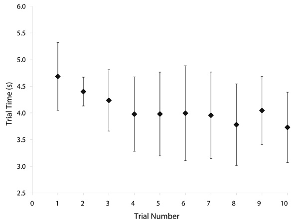
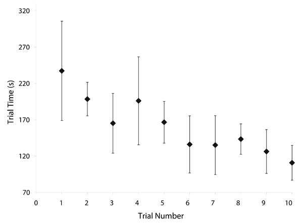
The average trial times versus the trial number for the actual arm and the robotic arm are plotted in Fig. (10) and Fig. (11) respectively. The error bars in each plot represent ± one standard deviation.
As can be seen in the plots of the robotic arm trials the data points appear to be oscillatory with large standard deviations. This effect was observed to be from variations in learning patterns between subjects. Some subjects were more aggressive with their attempts while others preferred to take a more steady approach to their learning. About half the subjects had an initial increase in performance followed by a large decrease in performance as seen in trial four with the large mean and standard deviation. At this point some of the subjects had become overconfident in their skills and started taking too many risks. After this blip subjects started to gradually improve their times again, but still with some oscillations in performance.
From the trials where the subjects used the robotic arm, the mean trial time from the first trial was found to be significantly greater than the mean trial time from the tenth trial (p < 0.005). This result suggests that on average the subjects improved their skill in myoelectric control over the course of the trials. Comparing the subjects’ trial times between the baseline of using their actual arm versus the robotic arm indicates that the current gap in functionality between an intact and myoprosthetic limb is still very large. Clearly, there is much room for improvement over the conventional myoelectric control scheme used in this study.
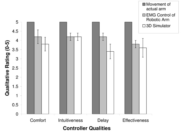
Fig. (12) plots the controller evaluation results from the usability survey. The error bars in the plot represent the standard error in the means. All subjects rated their actual arm with a score of five with no variation. The scores of the simulator came in slightly lower than scores of the robotic arm, but the differences were not significant, (p > 0.05).
Fig. (13) shows the average difficulty rating for each DoF on the robotic arm. Hand open/close, wrist flexion, and elbow flexion were all rated similarly with no statistically significant differences. However, shoulder rotation was significantly more difficult to use than the other three DoF (p < 0.005). This result was also reflected in the subject’s comments with several subjects mentioning the shoulder rotation could have been smoother.
While the subjects performed their trials their user errors and any issues with the MTT were observed. The most common type of user errors were over cycling and just passing the desired DoF on the switch list. Correspondingly, the most common comment from subjects on the usability survey was the suggestion to add in an additional myoelectric channel in order to be able to cycle up and down the switch list. Another error was for subjects to initially move in the incorrect direction before moving in the correct direction especially with the rotation DoF, which was the least intuitive. Since the robotic arm mechanism moved the gripper towards or away from the balls as it closed and opened respectively a common error was for subjects to incorrectly position the gripper. Positioning the gripper too closely to the box floor would result in the gripper getting stuck on the floor or pinching the towel, while positioning the gripper too far away from the ball would result in the gripper entirely missing the ball. In some cases the subjects also dropped the balls or knocked them into the corners, which was perhaps the most time costly error. Some of the subjects also initially had difficulties early in their trials figuring out how to coordinate the positioning of the elbow and wrist flexion DoF.
Another common error was for subjects to bang into the walls or floor of the boxes and cause the servos to overload and automatically shutdown to help prevent damage. The most common servos to overload were the ones controlling the elbow DoF since they were the ones that carry the most load. The number of elbow shutdowns that occurred over the course of the trials for each subject ranged from zero to six. However, some of the shutdowns appeared to occur intermittently for no discernible reason. After the trials were completed this issue was investigated and it was found that when the elbow DoF moves very slowly the elbow servos, which run on separate controllers built into the servo housings, tend to move different angular distances and become misaligned significantly overloading one servo. A solution to this problem that was tested and confirmed to work was to send commands to the elbow servos to realign every time the elbow DoF comes to rest. Another solution is to exchange the AX-12 servos for the recently released higher and stronger torque AX-18F servos. The AX-18F servos have exactly the same form factor as the AX-12 servos and are compatible to run on the same Dynamixel bus.
3.2. Design Compliance and Future Work
A design compliance matrix was created in order to verify whether the MTT prototype met the design requirements. After reviewing the requirements closely it was determined that the MTT prototype met or exceeded all of the requirements. Small issues along with suggested improvements for the future MTT prototypes are outlined below.
In the mechanical subsystems, the main deficiency with the AX-12 Smart Arm is that it is not anatomically correct. A future improvement could include redesigning the brackets in order to more closely follow anatomical proportions. The bracket redesign could include a new shoulder joint that is able to move more smoothly. A casing or sleeve could also be designed to help improve the aesthetics of the robotic arm and make it more closely resemble an actual myoelectric prostheses.
In the electrical subsystems, the servos for the elbow DoF should be replaced with the higher torque versions to prevent misalignment. A custom signal conditioning board should be developed that includes an anti-aliasing filter and additional layers of safety isolation that meet CSA 60601 standards. To increase the portability of future MTT prototypes the target computer and DAQ card will be replaced with embedded hardware that can fit inside a shoe box sized enclosure and the host computer should be replaced with a laptop. Design work on this future prototype is currently underway with the goal of ultimately being able to fit the entire system into a suitcase that can easily be shipped to remote locations.
In the software subsystems, a feature should be implemented in the EMG controller to allow the subjects to cycle up or down the switch list. A custom API should also be written to communicate with the AX-12 or AX-18F servos so that they can be controlled via a real-time xPC Target kernel. The GUI should add in functionality for recording the muscle signals over time in record files that can be analyzed remotely by therapists. The simulator should be expanded to include a dynamic model of the robotic arm that will allow it to pick up objects and interact with the environment. A valuable addition to the MTT would be to develop a custom software interface that will allow the patients to train using myoelectrically controlled video games.
A future study should be performed to test subjects ability to control two DoF freedom simultaneously. Also, the MTT can be used in studies to evaluate pattern-recognition controllers against conventional controllers. After the clinical prototype of the MTT is completed clinical trials should be performed with amputee patients as subjects and attempt to establish the effect of the MTT on clinical outcomes.
CONCLUSIONS
In conclusion, a research prototype of the MTT has been designed and built. The prototype improves upon previous commercial myoelectric training systems with support for two DoF to be controlled simultaneously by four EMG channels and a fifth channel available to be used as a switch. The system can control a five DoF robotic arm in both a physical or simulated form. This system is well suited to be used with TMR and non-TMR amputee patients alike. The system has been designed to be modular so that it can also be used to test new experimental myoelectric control schemes. Initial testing and experimental studies were performed and indicate that the completed MTT research prototype has met its core design requirements and is well on its way to meeting the overall project objectives. Future work will focus on improving the portability of the MTT and getting it ready for clinical studies to be performed on amputee patients.
CONFLICT OF INTEREST
None declared.
ACKNOWLEDGMENTS
The authors would like to thank A. Alloway, J. Duncan, K. Hensel, R. Miller, and J. Tam for their work designing the initial version of the MTT simulator. The authors also gratefully acknowledge contributions and financial support from the Glenrose Rehabilitation Hospital.