All published articles of this journal are available on ScienceDirect.

Unicompartmental Knee Resurfacing: Enlarged Tibio-Femoral Contact Area and Reduced Contact Stress Using Novel Patient-Derived Geometries
Abstract
Advances in imaging technology and computer-assisted design (CAD) have recently enabled the introduction of patient-specific knee implant designs that hold the potential to improve functional performance on the basis of patient-specific geometries, namely a patient-specific sagittal and coronal curvature, as well as enhanced bone preservation. The objective of this study was to investigate the use of a novel implant design utilizing a patient specific sagittal J-curve on the femoral component combined with a novel constant, patient-derived femoral coronal curvature and to assess tibio-femoral contact area and contact stress on a femur matched curved tibial polyethylene insert.
Mean contact area and standard deviations were 81±5, 96±5 and 74±4 mm2 for the heel strike, toe off and mid-stance positions, respectively. Mean contact stress and standard deviations were 23.83±1.39, 23.27±1.14 and 20.78±0.54 MPa for the heel strike, toe off and mid-stance positions, respectively. Standard deviations of the measurements were small, not exceeding 6-7% confirming the consistency of loading conditions across different flexion angles. The results were comparable to those reported for standard, off-the-shelf fixed-bearing implants with paired femoral and tibial geometries. These data show that a constant coronal curvature can be applied to a patient-specific implant by measuring coronal curvatures across the femoral condyle in each patient and by deriving an average curvature. This novel approach combines unique benefits of patient-specific geometry with proven design concepts for minimizing polyethylene wear.
INTRODUCTION
Osteoarthritis of the knee is a growing epidemic affecting more and more young and middle aged patients [1]. The rate of unicompartmental knee arthroplasty (UKA) is growing three times faster than that of total knee arthroplasty (TKA) [1]. Excellent, dependable clinical results in the first decade encouraged surgeons to expand the indication for UKA to younger and more active patients [2]. There are several key benefits of UKA as compared to TKA. Postoperative range of motion is better, the knee feels more normal [3, 4] and the incidence of postoperative complications, such as deep venous thrombosis, pulmonary embolism and infection, are lower as compared with total knee replacement (TKA) [5-8].
In spite of these advantages, the total number of UKAs performed in 2007 was only 8% of all arthroplasty procedures [1]. The incidence of unicompartmental knee osteoarthritis with preservation of the other two compartments is, however, reported to range between 6 and 40% [9, 10]. A major reason why UKA is still only used in a small percentage of patients lies in the fact that UKA is technically more demanding than TKA. There are also significant limitations in current implant designs. The implants do not match the anatomy accurately; some implants are narrower than others. High early failure rates have been reported in obese patients in designs with an inset or narrow tibia [6], while early results with a wider tibial component did not show increased early failure rates in patients with a body mass index (BMI) >32 [11]. Most systems are gradually changing to asymmetric femoral components to improve implant fit and to reduce the risk of edge-loading. Design flaws persist on the lateral side. The lateral side of the tibial plateau is more convex than the medial side. The tibial components do not match the AP/ML ratio of the tibial plateau. Experienced surgeons use tricks to compensate for these shortcomings. The tibial component is moved more medially, not covering the most lateral aspect of the tibial plateau and the femoral component is erred as lateral as possible. The lateral condyle is smaller and over-sizing of the femoral component results in patellafemoral impingement.
Personalized, patient-specific implants can address the shortcomings of current off-the-shelf implants and can improve bony coverage on the tibia as well as on the femoral side. A resurfacing femoral design can anatomically resurface the femoral condyle, eliminate femoral chamfer cuts and restore knee kinematics as close as possible as compared to the normal anatomy. The tibial component can cover the entire tibial cortex with expected improvements in the rate of tibial implant subsidence and loosening. This is not only beneficial on the medial side but can be particularly helpful in the lateral compartment, preempting the design limitations of current implant designs.
Patient-specific implant designs offer many advantages over traditional, off-the-shelf implant designs. One of the potential limitations of a completely patient specific design is the variability in coronal curvature of the femoral component, which may result in point loading in select flexion angles when a curved tibial insert is used. To address this problem, a flat polyethylene tibial component is paired with the constant coronal curvature femoral component, which ensures constant loading conditions over a large area irrespective of flexion angle. This implant design is the only patient specifically designed unicompartmental implant system available on the market today.
In the present paper, we investigated the use of a novel implant design that utilizes a patient-specific sagittal J-curve on the femoral component combined with a constant, patient derived femoral coronal curvature. This femoral component design allows the use of a tibial polyethylene insert or component with a convex curvature matched to the femoral coronal geometry. The effect of this novel design on tibio-femoral contact area and stress was evaluated.
MATERIALS AND METHODOLOGY
Computer-Assisted Design (CAD)
The femoral component, tibial tray, tibial insert and tray fixtures were designed by ConforMIS, Inc. (ConforMIS, 2 Fourth Ave., Burlington, MA 01803). The process of manufacturing a patient-specific implant is briefly described below.
When it is determined that a patient has an indication for a unicompartmental knee replacement, the patient is sent for a CT scan. The CT scan is conducted according to a standard protocol, which prescribes that the full knee and a portion of the hip and ankle will be imaged using spiral CT imaging. Representative CT parameters are shown in Table 1. The CT images are uploaded to a secure web server and the images are imported into the proprietary implant manufacturing software. Within the software, the first step is to derive the outer contour of the bone, which is done via proprietary algorithms. Surface data are generated for further processing.
Representative CT Protocol for Generating Patient Specific Resurfacing Implants
| Scan | Area of Interest | Kernel/Algorithm | Axial Reconstruction Thickness X Increment | Multi Planar Reformat MPR |
|---|---|---|---|---|
| 1 | Scout – Hip through Ankle | |||
| 2 | Hip – Femoral head only | Bone | 2 – 2.5 X 2 – 2.5 | N/A |
| 3 | Knee – Top of patella to 3 cm below the tibial plateau | Bone | 1 – 1.5 X .5 – .625 | 1 mm X 1 mm Sagittal and Coronal |
| 4 | Ankle – Malleoli through Talus | Bone | 2 – 2.5 X 2 – 2.5 | N/A |
Test Results for Different Inserts
| Insert# | Position | Flexion (degree) | Applied Force (Newton) | Contact Area (mm2) | Peak Contact Stress (MPascal) |
|---|---|---|---|---|---|
| 1 | Heel | 0 | 1171 | 79.03 | 25.34 |
| 1 | Toe off | 15 | 1367 | 88.71 | 23.47 |
| 1 | Midstance | 20 | 889 | 69.36 | 21.05 |
| 2 | Heel | 0 | 1182 | 75.81 | 25.07 |
| 2 | Toe off | 15 | 1359 | 91.94 | 24.95 |
| 2 | Midstance | 20 | 884 | 69.36 | 21.69 |
| 3 | Heel | 0 | 1171 | 79.03 | 24.77 |
| 3 | Toe off | 15 | 1365 | 100.00 | 23.09 |
| 3 | Midstance | 20 | 884 | 72.58 | 20.35 |
| 4 | Heel | 0 | 1165 | 88.71 | 22.06 |
| 4 | Toe off | 15 | 1359 | 101.61 | 21.48 |
| 4 | Midstance | 20 | 887 | 80.65 | 20.72 |
| 5 | Heel | 0 | 1175 | 80.65 | 23.00 |
| 5 | Toe off | 15 | 1363 | 95.16 | 23.79 |
| 5 | Midstance | 20 | 884 | 75.81 | 20.67 |
| 6 | Heel | 0 | 1173 | 83.87 | 22.76 |
| 6 | Toe off | 15 | 1363 | 96.77 | 22.84 |
| 6 | Midstance | 20 | 884 | 75.81 | 20.20 |
Summary of Contact Area Measurements
| Insert # | Full Extension (mm2) | Toe Off (mm2) | Mid Stance (mm2) |
|---|---|---|---|
| 1 | 79 | 89 | 69 |
| 2 | 76 | 92 | 69 |
| 3 | 79 | 100 | 73 |
| 4 | 89 | 102 | 81 |
| 5 | 81 | 95 | 76 |
| 6 | 84 | 97 | 76 |
| AVG | 81 | 96 | 74 |
| STD | 5 | 5 | 4 |
Summary of Contact Stress Measurements
| Insert # | Full Extension (MPascal) | Toe Off (MPascal) | Mid Stance (MPascal) |
|---|---|---|---|
| 1 | 25.34 | 23.47 | 21.05 |
| 2 | 25.07 | 24.95 | 21.69 |
| 3 | 24.77 | 23.09 | 20.35 |
| 4 | 22.06 | 21.48 | 20.72 |
| 5 | 23.00 | 23.79 | 20.67 |
| 6 | 22.76 | 22.84 | 20.20 |
| AVG | 23.83 | 23.27 | 20.78 |
| STD | 1.39 | 1.14 | 0.54 |
With a surface model now residing as a virtual model the patient-specific bone geometry and surface data are used to direct additional proprietary software that generates the implant geometry. The implant geometry is designed to ensure a minimum component thickness of 3.0 mm for the femoral component and 2.0 mm for the metal backing of the tibial component. The process results in a patient-specific unicompartmental femoral component (Fig. 1) in the CAD system. The patient’s bone defines the sagittal geometry of the femoral component. Thus, the sagittal geometry is completely patient specific; the resultant sagittal implant radii vary along the anteroposterior dimension of the implant (Figs. 1 and 2). A minimal posterior bone cut of approximately 3–4 mm is incorporated into the design to facilitate implant placement based on the patient’s posterior condylar geometry and orientation.
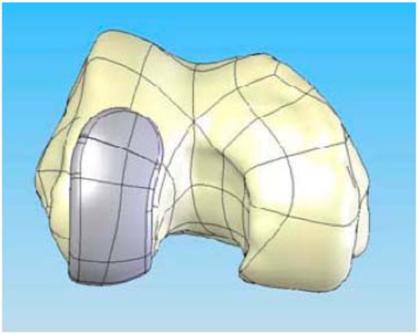
CAD image of the patient-specific iUni femoral component on the distal femur.
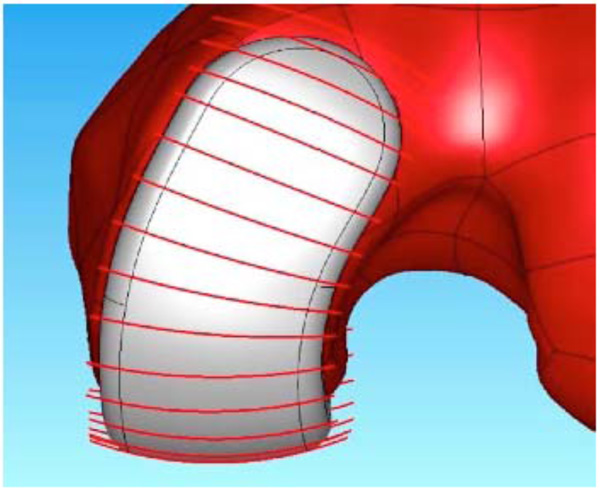
Lateral view of the patient-specific iUni femoral component. Sagittal radius varies along the anteroposterior dimension of the femoral component reflecting the patient’s sagittal anatomy.
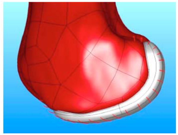
Frontal view of the patient-specific iUni femoral component. The red lines indicate the location where the patient’s coronal curvature is measured. The measurements are used to derive a mean coronal curvature for each patient which is then used to apply a constant coronal curvature along the bearing surface of the femoral component.
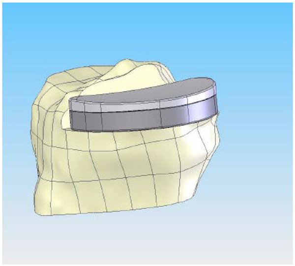
CAD image of the patient-specific tibial implant. The perimeter of the implant is matched to the cortical edge and the poly curvature is matched to the coronal radius of the femur at a specific ratio.
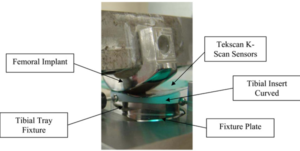
Test set-up for assessing contact area and contact stress.
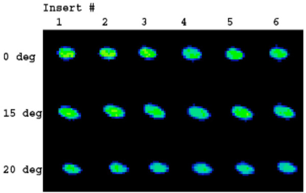
Contact stress images acquired with Tekscan K-Scan sensors. The load distribution is homogenous for the different positions and polyethylene inserts.
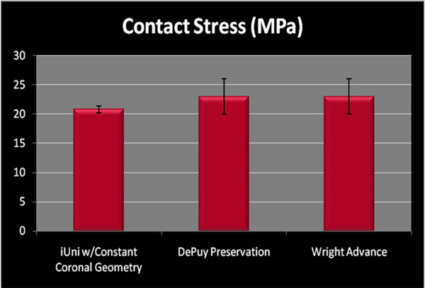
Peak contact stress in mid-stance position measured for patient specific unicompartmental implant with patient derived, constant coronal curvature (mean 20.78, SD 0.54) as compared to standard, off-the-shelf devices.
The coronal curvatures of the patient are measured at multiple positions along the length of the femoral condyle. An average curvature is then derived for each patient. The average curvature is adjusted to maintain a minimum implant thickness of greater than 3 mm. Using this approach, a patient derived constant coronal curvature is achieved (Fig. 3).
With a surface model now residing in the CAD program showing the correct spatial orientation of the knee, the technology then determines the deformity present in the patient. The iFit process interactively defines the extent of misalignment present in the knee, virtually realigns the knee to a neutral biomechanical axis, and designs the axis correction into the implants and disposable iJig™ instrumentation.
On the tibial plateau, the profile of the patient’s tibia (Fig. 4) defines the geometry of the tibial implant. In this method, the patient receives an implant that is not only optimized for fit, but it is also optimized for reduced contact stress in the polyethylene insert. The optimized contact stress is achieved by maintaining the same coronal conformity ratio regardless of implant size. The modular tibial plateau and tibial inserts are designed on a minimal bone cut and provide a smooth articulating surface for the femoral component. Importantly, because the implant is patient specific, it provides the potential for complete cortical rim coverage (>95%) (Fig. 4), a result that cannot be achieved with off-the-shelf implants [12]. The placement of the fixation features for that patient is based on design principles for unicondylar implants [13].
Femoral Component
The femoral components are manufactured in cobalt chrome conforming to ASTM (American Society for Testing and Materials) F-75-07 International Standards (http://www.astm.org/). The sagittal geometry of the femoral component is always fit exactly to the patient’s geometry since it is designed around the patient’s CT scan. In the coronal plane, the component has a constant radius that is derived from the patient’s unique anatomy (Figs. 2 and 3). Intraoperatively, remaining cartilage is removed and the femoral component sits on the subchondral bone, substantially preserving the underlying bone stock. The only bone cut on the femoral side is a small posterior cut that is typically between 3–6 mm.
Tibial Component
The tibial implant is a modular design with a geometry defined by the patient’s tibia, which allows for load bearing on the cortical rim (Fig. 4). Fully assembled, the tibial components are 8 mm or 10 mm in total thickness, including both the metal backed tray (2 mm) and polyethylene insert (6 or 8 mm). The tibial tray is the same alloy as the femoral component. The insert pocket is highly finished to reduce backside wear of the insert. The locking mechanism is based on a snap design. The snap has a posterior slide and an anterior elastically deformable snap. The insert is slid into the posterior portion of the tray and then is pressed down in the anterior region to engage the snap using an interference fit design. The anterior snap is not loaded by normal knee forces when it is snapped into the tibial plateau. Tibial tray fixation is with two pegs, a posterior fixation keel and cement. A cement containment rim is also present on the inferior surface of the metal tray.
The modular tibial inserts are provided in GUR 1020 UHMWPE material which is direct compression molded. Each implant set includes both a 6 mm and an 8 mm polyethylene insert. The articular geometry has a slight curvature in both the coronal and sagittal planes. The curvature is patient specific, and is designed based on the patient’s unique anatomy.
Testing
All testing was conducted at the Shiley Center for Orthopedic Research and Education Center (SCORE, 11025 N. Torrey Pines Road, Suite 140, La Jolla, CA, 92037) using multi-axial servohydraulic testing apparatus. (Force 5, Advanced Material Technology, Inc., Watertown, MA, 02472-4800).
The femoral implant was designed and fabricated using standard production processes so that the articular surface was complete and polished with an added feature for attaching the component to the testing apparatus (Fig. 5).
The bottom of the tibial tray was modified so that it could be fixed to the test frame. Six curved tibial insert sets (labeled inserts 1–6, Table 2) were tested using this experimental set-up with contact area and contact pressure measured for heel strike, toe off and midstance (see below). Contact area and peak contact stress on the tibial insert were measured with thin pressure sensitive sensors (K-Scan, Tekscan, Inc., 307 West First Street, South Boston, MA 02127-1309) inserted between the articulating surfaces. The sensors are in an array with a spatial resolution of 400 sensels per sq. in. The Tekscan sensors were preconditioned per manufacturer’s specifications.
The femoral component was cemented to a steel femoral adapter on a Force 5 machine and compressive force was applied at the following knee flexion and load conditions described by Morra [14].
- Heel strike (00) at 1170N
- Toe off (150) at 1356N
- Mid-stance (200) at 880 N
Normal saline was used as a lubricant between the femoral and tibial components. Tekscan images were acquired for the different positions (Fig. 6). These data were recorded at 100Hz via a USB module and converted to contact area (mm2) and contact stress (MPa) using the manufacturer’s calibration protocol.
Statistical Methods
All data relating to study were summarized using descriptive statistics such as mean, range, quartile and standard deviation. Analysis of variance (ANOVA) methods were used at the 5% level of significance to compare mean values of insert number and different positions of flexion for contact area and peak contact stress. Tukey’s multiple comparison tests was used for post hoc analysis. All statistical analysis tests were performed with the Statistical Analysis Software 9.1 (SAS Institute, Cary, NC, U.S.A.).
RESULTS
Test results for inserts 1 through 6 for heel strike, toe off and midstance are given in Table 2. The summary of contact area and contact stress is provided in Tables 3 and 4, respectively.
Contact Area
Contact area varied between 69 and 102 mm2. The means ranged between 74 and 96 mm2 for the different positions; the greatest mean contact area was observed in toe off position with a mean of 96 mm2. Of note, standard deviations of the measurements were small not exceeding 6–7% confirming the consistency of loading results (Table 3).
Analysis of variance method demonstrated that there was no statistically significant difference in contact area between the inserts (p≤0.8197). There was a statistically significant difference in the mean contact area at different flexion angles (p≤0.0001).
Contact Stress
Contact stress varied between 20.20 and 25.34 MPa. The means ranged between 20.78 and 23.83 for the different positions; the greatest mean contact stress was observed in full extension with a value of 23.83. Of note, standard deviations of the measurements were small not exceeding 5% confirming the consistency of loading results (Tables 3 and 4). The peak contact stress as measured did not vary substantially at the tested angles of flexion and extension. Tekscan images (Fig. 6) demonstrated a homogeneous load distribution across the inserts in different positions of flexion and extension, i.e. heel strike, toe off and midstance.
There was no statistically significant difference in contact stress between the different inserts (p≤0.5829); however, there was a statistically significant difference in the mean contact stress at different flexion angles (p≤0.0005). The grouping of different positions of flexion means resulting from the application of Tukey’s test indicates that the midstance position of flexion produces a lower score than the other two positions of flexion angles (Heel Strike and Toe Off), whose means do not differ (Tables 3 and 4).
DISCUSSION
Several studies have compared fixed bearing and mobile bearing results [15-19]. Emerson [15] reported that survivorship analysis based on component loosening and revision showed no statistically significant difference between fixed-bearing and mobile-bearing implants. The authors concluded that “both groups functioned well clinically.” Confalonieri [16] reported comparable results in Knee Society Scores when comparing fixed-bearing and mobile-bearing implants. Glesson [17] studied a total of 47 Oxford mobile-bearing and 57 St. George sled fixed-bearing unicompartmental implants. At two years, the pain component of the Bristol Knee Score was significantly better (p≤0.013) for the fixed-bearing group. Three patients in the fixed-bearing group required revision (mean time to revision 3.4 years) while in the mobile-bearing group three patients had bearing dislocations and an additional four patients required revision (mean time to revision 3.0 years). Glesson [17] concluded that in the short-term the mobile-bearing implants had a higher re-operation rate and that the fixed-bearing device provided superior pain relief. The functional scores for the two groups were, however, similar. Borus [20] concluded that both fixed- and mobile-bearing implants can yield excellent clinical outcomes at >10 years, but with different modes of failure.
Contact area and contact stress are one of the key determinants for long-term survival of fixed-bearing unicompartmental implants. Higher contact stresses result in a higher propensity for abrasive damage to the polyethylene and accelerated polyethylene wear. In addition, Bartell [21] first discovered that minor variations in coronal conformity can have a much greater effect on reducing contact stress than variations in sagittal conformity. Morra [22] showed that contact stress images (Fig. 6) provide an indication of areas where surface abrasion caused by contact with the femoral component can occur. Tekscan images acquired with the resurfacing implant with a patient-specific sagittal curvature and a patient-derived constant coronal curvature showed that the introduction of a constant coronal curvature helps to achieve consistent loading across different polyethylene inserts for different degrees of flexion and extension even when a curved polyethylene surface is used (Fig. 6, Table 4). Furthermore a curved coronal geometry on the femoral component allows for minor variations in placement of the femoral component that could affect contact stress. The constant coronal radius of the femoral component acts like a small radius that, when tangent to the larger radius of the constant coronal radius of the tibial articular surface, still presents that same contact area regardless of minor (<10 degrees) coronal malalignment. Moreover, the use of patient-specific jigs reduces the possibility of alignment error between the components and relative to the mechanical axis. A recent report indicates highly accurate postoperative alignment using these personalized alignment jigs, with preoperative varus alignment of mean 6.8 degrees (SD 3.3 degrees) and postoperative alignment of 0.8 degrees (SD 1.5 degrees) [Evaluation der Implantatpositionierung und Beinachskorrektur nach Patienten-spezifischem unikompartimentellem Kniegelenkersatz, Franz X. Köck (Bad Abbach), J. Beckmann, C. Lüring, B. Rath, J. Grifka, E. Basad. 58. Jahrestagung der Vereinigung Süddeutscher Orthopäden e. V. (VSO) / Evaluation of implant position and leg axis correction after patient-specific unicompartmental knee replacement. Franz X Koeck (Bad Abbach, Germany), J. Beckmann, C. Luering, B. Rath, J. Grifka, 58th Annual Meeting of the Association of South German Orthopedic Surgeons].
Fig. (7) compares the mean peak contact stress in midstance as measured on the iUni with contact pressure data published by Morra [14] for two similar unicondylar implants. Of note, the data generated by Morra on the other two fixed-bearing implants is obtained using computational methods. Results for the patient-specific resurfacing implant are based on physical testing with the Tekscan system, which has been widely used for contact measurement experiments in many applications and reported for knee results for many years [23]. The Tekscan pressure sensitive film consists of a 2 layer film. On the inner surface of one film, a column pattern of electrically conductive nodes are deposited. On the inner surface of the opposite film, a row pattern of electrically conductive nodes are deposited. The two films are bonded together. When pressure is applied to the thin film, the column and row patterns in the area of the applied load complete a circuit. The column and row patterns can be placed as close together as 0.5 mm. When conductivity of a node is sensed, the signal is processed and converted into a pressure for that node. Multiple conducting nodes measure the total pressure over a specifically loaded area. The other accepted method for contact pressure measurement in implant systems is the Fujifilm Prescale (FUJIFILM North America Corporation, Valhalla, NY). Fuji film is a tactile pressure indicating film that contains a layer of tiny microcapsules. The application of force upon the film causes the microcapsules to rupture, producing an instantaneous and permanent high resolution "topographical" image of pressure variation across the contact area. These two methods are similar in that they are both films that are placed between two components for the purposes of measuring both contact areas and contact stress.
Although these are 2 different experimental methods, the results indicate that a resurfacing implant with patient-specific sagittal geometry and a patient-derived constant coronal curvature can achieve contact pressure and contact areas that are comparable to those achieved with standard fixed-bearing implants that use fixed, paired femoral and tibial geometries.
CONCLUSION
Advances in imaging technology and computer-assisted design (CAD) have recently enabled the introduction of patient specific knee implant designs that hold the potential of improved functional performance on the basis of patient-specific geometries, namely a patient-specific sagittal J-curve, as well as enhanced bone preservation. One of the limitations of this approach has been the variability in the patient’s femoral coronal curvature along the condyle, which required the use of flat tibial component designs in order to avoid point loading. The current work shows that a constant coronal curvature can be applied to a patient-specific implant by measuring coronal curvatures across the femoral condyle and by deriving an average curvature. A patient-derived constant coronal curvature allows the use of a femur matched, curved, convex tibial polyethylene insert. The resultant contact area and contact stress is comparable to that reported for standard, off-the-shelf fixed-bearing implant designs with fixed, paired femoral and tibial geometries. Tibiofemoral contact pressures observed for the resurfacing implant with patient-specific sagittal geometry and patient-derived constant coronal curvature are homogeneous for different flexion and extension angles. This novel approach combines unique benefits of patient-specific geometry with proven design concepts for minimizing polyethylene wear.