All published articles of this journal are available on ScienceDirect.
Patient-Specific Unicompartmental Knee Resurfacing Arthroplasty: Use of a Novel Interference Lock to Reduce Tibial Insert Micromotion and Backside Wear
Abstract
Micromotion has long been associated with wear of polyethylene tibial inserts, potentially causing failure of unicompartmental knee replacement systems. One cause of micromotion is the locking mechanism between the undersurface of the polyethylene and the tibial tray. The objective of this study was to investigate the use of new novel lock designs for reducing the micromotion associated with a patient specific tibial implant. Micromotion occurring between the tibial insert and tibial tray was measured using the DVRT method for two new lock designs and compared to the micromotion measured for the prior generation lock design. In total, 18 samples were tested, six in each of the three designs: prior generation CLEARANCE lock design, new LINE-TO-LINE design, new INTERFERENCE design.
At the lowest loading of 100N, the motion index of the new interference lock design (4.9 ±2.6 microns) was less than the motion index of both the new line-to-line lock design (11.9±4.5 microns) and the prior generation clearance lock design (154.9±84.4 microns). Likewise, at the higher loading of 400N, the motion index of the new interference lock design (58.7 ±7.2 microns) was again less than the motion index of the two alternative lock designs (new line-to-line: 135.5±57.6 microns; prior generation clearance: 371.8±151.4 microns). When compared to previously published micromotion data for TKR systems, the results demonstrate that a novel interference design locking mechanism as part of a patient-specific unicompartmental knee arthroplasty system can significantly reduce micromotion that is believed to be one of the causes of osteolysis.
INTRODUCTION
Modularity of tibial inserts has been hotly debated over the past 10 years or so. Parks et al. [1] reported severe polyethylene wear on the backside of modular tibial inserts in 1994. Other researchers have reported similar findings [2, 3]. The issue of polyethylene wear on modular tibial inserts was brought to the forefront by Fehring in 2004 with his study on osteolysis in the PFC Knee system in which the prevalence of wear-related failure was reported to be 8.3% [4]. In this study, three variables related to the polyethylene, polyethylene sheet vendor, polyethylene finishing method, and polyethylene shelf age, were correlated with the wear-related failure due to resulting micromotion between the undersurface of the polyethylene and the tibial tray [4]. While some undersurface motion may be inevitable, studies have also indicated that a secure locking mechanism and a highly finished cobalt chrome tibial tray may help to reduce backside wear and subsequently reduce micromotion and osteolysis. A study analyzing three modern total knee designs with different locking mechanisms concluded that the locking mechanism greatly affects the wear [5]. More recently, a study was published which explored the fretting wear of polyethylene against metal as a function of the metal surface finish, and concluded that the greatest reduction in polyethylene wear was achieved by highly polishing the metal surface [6].
In the current study, we investigated the use of a novel interference lock for reducing micromotion and backside wear in a patient -specific unicompartmental resurfacing device (iUni®). The iUni is an FDA cleared and CE Marked unicompartmental resurfacing device designed for patients with arthritic damage isolated to either the medial or lateral tibiofemoral compartment of the knee. The patient-specific implant is designed from a CT scan of an individual patient's knee using a software driven design process. The cobalt chrome femoral component conforms to the surface of the patient's femoral condyle, replacing the damaged cartilage with a smooth articulating surface. The geometry of the tibial implant is specified to provide full cortical rim coverage on the tibia, therefore reducing the risk of implant subsidence and loosening.
The design of the locking mechanism between the polyethylene insert and the tibial tray has been optimized to reduce micromotion using a novel interference mechanism. The purpose of this study was to validate the performance of the interference locking mechanism by testing the amount of micromotion occurring at the tibial insert and tibial tray interface. Comparison was made between the prior generation, non-interference lock tibial inserts and tibial trays, and two new interference lock designs. The hypothesis is that the interference lock designs will yield less micromotion than the non-interference lock design, therefore reducing the potential for osteolysis.
MATERIALS AND METHODS
The patient-specific iUni device was designed by ConforMIS, Inc. (Burlington, MA USA).The femoral component is manufactured in cobalt chrome molybdenum according to ASTM (American Society for Testing and Materials) F-75-07 International Standards (http://www. astm.org/). The tibial component is a modular design with a geometry defined by the patient’s tibia from a CT scan. The modular design of the tibial component allows for load bearing on the cortical rim and, because the implant is patient-specific, it provides for tibial coverage designed to a standard of greater than 95% of the cut tibial surface (Fig. 1). Fully assembled, the tibial components are 8mm or 10mm in total thickness, including both the metal backed tray (2mm) and polyethylene insert (6mm or 8mm). The tibial tray is the same alloy as the femoral component. The insert pocket is highly finished to reduce backside wear of the insert. The locking mechanism is based on a snap design. The snap has a posterior slide and an anterior elastically deformable snap. The insert is slid into the posterior portion of the tray and then is pressed down in the anterior region to engage the snap using an interference fit design. The anterior snap is not loaded by normal knee forces when it is snapped into the tibial plateau. Tibial tray fixation is with two pegs, a posterior fixation keel and cement. The placement of the fixation features for each patient is based on design principles for unicondylar implants [7]. A cement containment rim is also present on the inferior surface of the metal tray.
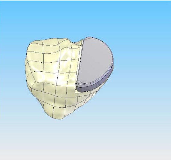
CAD image of the patient-specific iUni tibial implant. The perimeter of the implant is matched to the cortical edge thereby achieving cortical rim support all around. This design feature helps to reduce the potential for tibial subsidence compared to standard, off-the-shelf devices.
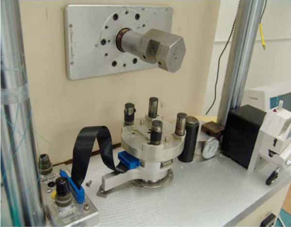
AMTI Force 5 Servohydraulic Testing System.
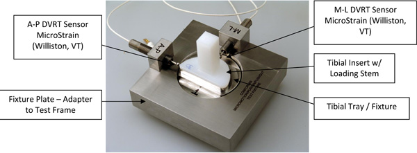
Custom Baseplate with Tibial Insert.
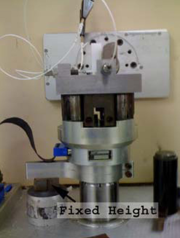
Test Fixture on Test Frame.
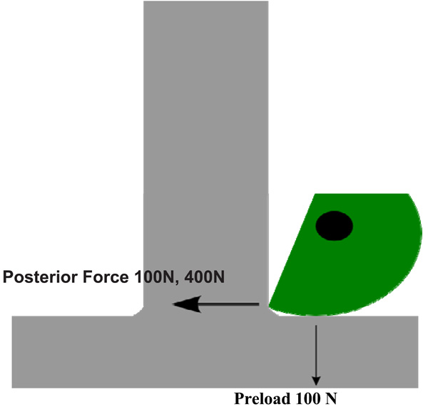
Applied Forces.
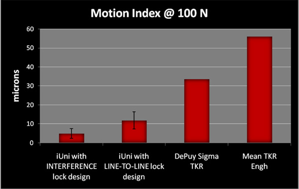
Motion Index results for iUni INTERFERENCE and LINE-TO-LINE lock designs versus DePuy Sigma TKR and Mean of 5 TKR systems with snap-fit locking mechanisms from paper by Engh (8).
The modular tibial inserts are provided in GUR 1020 UHMWPE material which is machined out of direct compression molded blocks. Each implant set includes a 6mm and an 8mm polyethylene insert option. The articular geometry has a slight curvature in both the coronal and sagittal planes. The curvature is patient-specific, and is designed based on the patient’s unique anatomy as determined by the CT scan.
Biomechanical Testing
All testing was conducted at the Shiley Center for Orthopedic Research and Education Center (SCORE, LaJolla, CA, USA) using the AMTI Force 5 knee simulator. The AMTI Force 5 knee simulator is a multi-axial servohydraulic testing apparatus which replicates the loading and full range of multi-axis motion associated with activities of daily living for purposes of biomechanical testing. The test set-up is shown in Figs. (2-5).
A total of 18 specimens were tested in three stratified groups of six. The first group of six specimens utilized the previous generation CLEARANCE lock design in which the tibial inserts had a clearance of 0.10mm to 0.20mm with respect to the tibial tray. The second group of six specimens utilized a new LINE-TO-LINE lock design in which the inserts were manufactured to the smallest allowable dimensional specification resulting in a theoretical exact or LINE-TO-LINE fit. Finally, the third group of six specimens utilized a new INTERFERENCE lock design in which the tibial inserts were manufactured to the largest allowable dimensional specification resulting in an INTERFERENCE fit. The new lock designs had dimensional variances that represented the range of possible fits that can be encountered in normal production. The design allows for a minimum or line-to-line fit where the insert and tray are exactly the same size, to a maximum interference condition, where the insert is larger than the tray by 0.075 millimeters.
The following configurations were tested:
- CLEARANCE - 6 tibial inserts with current design in which the tibial inserts have a clearance of 0.10mm to 0.20mm with respect to the tibial tray (Samples 33 thru 38).
- LINE-TO-LINE - 6 tibial inserts with a new design of a theoretical exact fit between the tibial insert and the tibial tray (Samples 27 thru 32)
- INTERFERENCE - 6 tibial inserts with a new design in which the tibial inserts are 0.075mm larger than the tibial tray (Samples 5A thru 5F)
Tibial inserts were manufactured under normal manufacturing methods, but in this case a post was incorporated onto the articular surface to serve as a means to apply loads in the medial to lateral direction (ML) and in the anterior to posterior directions (AP). The tibial tray and insert were assembled and mounted on the Force 5 knee simulator using a custom base plate. The base plate design allowed 90° rotation of the fixture for AP and ML loading. A custom steel shaft was used to apply isolated horizontal shear force to the insert and 100N vertical preload. See Fig. (5).
The holding fixture in Fig. (3) was loaded into the AMTI Force 5 knee simulator and loads were applied according to the method described by Engh [8]. The measurements were tabulated for 12 different insert samples and a single tray sample.
To measure relative motion between the insert and tray directly in both the anterior-posterior direction and the medial-lateral direction, two MicroStrain (Williston, VT) gauging Differential Variable Reluctance Transducers (DVRT, a high performance miniature instrument used to measure critical linear displacement) were installed across the insert-tray interface. Each DVRT was rigidly attached to the base plate, while the spring-loaded probe was in contact with the edge of the plastic insert. The specimens were tested for 20,000 cycles with a sinusoidal waveform with peak load of 1500N at a frequency of 0.5Hz. It was not necessary to compensate for the spring because its k value was measured to be less than 0.01% of the applied shear forces as per manufacturer’s information. Shear forces of 100N and 400N were each applied at a rate of 10N per second. The following parameters were recorded: time (seconds), DVRT voltage (volts), and applied shear force (Newtons). DVRT calibration values were used to convert voltage to microns and calculate motion of the insert relative to the tray.
Statistical Methods
All statistical analyses and tests were performed on Statistical Analysis Software 9.1 (SAS Institute, Cary, NC) and all results were tested at a 5% level of significance. All data relating to micromotion between the tibial insert and the tibial tray, which occurred in all three configurations (CLEARANCE, LINE-TO-LINE and INTERFERENCE) and in both loading conditions (100N, 400N), was summarized using descriptive statistics. Comparison of mean values of loading conditions (100N and 400N) for the three configurations (CLEARANCE, LINE-TO-LINE and INTERFERENCE) was tested using Wilcoxon Mann-Whitney and Student t-test as non-parametric and parametric tests.
RESULTS
Results are shown in Table 1.
Micromotion between the tibial insert and the tibial tray occurred in all three configurations (CLEARANCE, LINE-TO-LINE and INTERFERENCE) and in both loading conditions (100N, 400N). In addition to micromotion, the motion index (MI) as formulated by G. Engh [8] was calculated as the resultant angle where
ap = the motion in the anterior to posterior direction
ml = the motion in the medial to lateral direction.
At the lowest loading of 100N, the current tibial insert/tray configuration (CLEARANCE) averaged 64.5 microns and 129.2 microns in the medial to lateral and anterior to posterior directions, respectively. The new LINE-TO-LINE design at the 100N loading condition yielded 5.2 microns and 10.2 microns in the medial to lateral and anterior to posterior directions, respectively. The new INTERFERENCE design at the 100N loading condition showed micromotion of 3.8 microns and 2.8 microns in the medial to lateral and anterior to posterior directions, respectively. The motion index was 154.9 microns for the CLEARANCE inserts, 11.9 microns for the LINE-TO-LINE inserts, and 4.9 microns for the INTERFERENCE inserts.
As expected, micromotion was greater at the higher loading condition (400N). At 400N, the CLEARANCE tibial insert/tray configuration micromotion averaged 598.0 microns and 299.0 microns in the medial to lateral and anterior to posterior directions, respectively. The new LINE-TO-LINE design at the 400N loading condition yielded 56.0 microns and 122.2 microns in the medial to lateral and anterior to posterior directions, respectively. For the new INTERFERENCE design at the 400N loading condition, the micromotion was 5.8 microns and 58.3 microns in the medial to lateral and anterior to posterior directions, respectively. The motion index was 371.8 microns for the CLEARANCE inserts, 135.5 microns for the LINE-TO-LINE inserts, and 58.7 microns for the INTERFERENCE inserts.
DISCUSSION
The use of knee replacement devices continues to grow with the aging and increasingly active population. The prevalence of patients with knee implants results in greater numbers of patients with implant failures. Osteolysis and subsequent wear-related failure of the tibial components of knee implants continues to be a problem [1]. An early study by Wasielewski concluded that there was a significant association between wear on the underside of the tibial base plate and radiographic evidence of osteolysis [2]. The wear at the modular interface can be abrasive and creates small particles which incite an osteolytic response. One of the causes of such wear is micromotion between the undersurface of the polyethylene and the tibial tray. In addition, studies have shown that there are several factors related to the polyethylene that may contribute to the micromotion [1, 2, 8]. These include polyethylene sheet vendor, polyethylene finishing method and polyethylene shelf age [2]. Manufacturers have worked to refine the design of the tibial components to minimize micromotion.
In addition, previous studies have concluded that backside wear and thus micromotion is significantly affected by the polyethylene insert locking mechanism and must be considered during component design [1, 5, 8], The novel new designs of the iUni tibial component (LINE-TO-LINE and INTERFERENCE) demonstrated significantly less micromotion than the CLEARANCE design. With the INTERFERENCE design, the motion index was significantly reduced at both the 100N load condition and the 400N load condition as compared to the CLEARANCE motion index at the same load conditions. At the 100N load condition, the motion index of the LINE-TO-LINE and INTERFERENCE designs demonstrated a decrease of 92% and 97% respectively as compared to the CLEARANCE motion index. At the 400N load condition, the motion index of the LINE-TO-LINE and INTERFERENCE designs demonstrated a decrease of 64% and 84% respectively as compared to the CLEARANCE motion index.
Although comparative data specifically on micromotion associated with unicompartmental knee implants has not been published to our knowledge, the LINE-TO-LINE and INTERFERENCE motion indices compare favorably to previously published data [1,9] (see Fig. 6). At the 100 Newton load condition, the mean resultant motion index for the iUni at the INTERFERENCE condition was 4.9 microns and the motion index of the iUni at the LINE-TO-LINE condition was 11.9 microns. Drawing on the available data for total knee tibial components may provide a practical benchmark to understand the relative performance of the unicompartmental tibial component. For comparative purposes, the DePuy Sigma total knee motion index has been reported to be 33.6 microns [9] and the mean motion index for all of the TKR implants utilizing a snap-fit locking mechanism measured in the Engh study was 56.1 microns [1]. The snap-fit locking design were the best performers in the study, and consistent with designs of tibial insert locking mechanisms in use today. See Fig. (6). It should also be noted that the compressive forces applied to the articular surface during functional activity may substantially reduce the micromotion relative to the unloaded condition [10].
The results of this study indicate that a novel interference design locking mechanism as part of a patient-specific unicompartmental knee arthroplasty system can significantly reduce micromotion that is believed to be one of the causes of osteolysis. Based on published micromotion implant studies, the performance of this novel interference lock design is better than that of standard off-the-shelf systems.
DISCLOSURE
This study was supported by funding from ConforMIS. No benefits, other than payment for the research study and analysis, have been received or will be received from a commercial company related directly or indirectly to the subject of this article. One of the authors, Nam Chao, is an employee of ConforMIS.

